
Ultra-clean chamber with backflow fan

A technology of ultra-clean rooms and fans, applied in the field of ultra-clean rooms, can solve the problems of low gas circulation efficiency and achieve the effect of accelerating air circulation efficiency

Active Publication Date: 2016-11-09
JIANGSU ZHONGHAN COMM TECH
View PDF8 Cites 0 Cited by
  • Summary
  • Abstract
  • Description
  • Claims
  • Application Information

AI Technical Summary

Problems solved by technology

The main problem of the existing ultra-clean room is that the circulation of gas only depends on the convection effect between the air inlet and the air outlet, and the gas circulation efficiency is low

Method used


Image

  • Ultra-clean chamber with backflow fan

Examples


Embodiment Construction

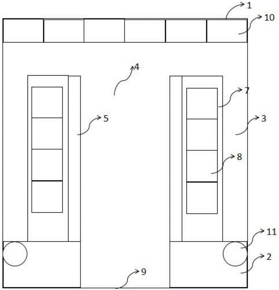
[0009] figure 1 is a schematic diagram of the present invention. Such as figure 1 As shown, the ultra-clean room of the present invention includes an air inlet end 1 arranged at the front end of the ultra-clean room, a return end 2 arranged at the rear end of the ultra-clean room and an air passage 3 arranged at the left and right sides of the inner side of the ultra-clean room; the ultra-clean room An operation channel 4 is arranged on the central axis of the left and right sides, and a lifting device 5 is arranged on both sides of the operation channel 4; a left and right transparent storage area 7 is arranged between the lifting device 5 and the air passage 3, and the storage area 7 A storage rack 8 is placed in the object area 7; a door 9 for the operator to enter and exit is also provided at the back end of the clean room; the door 9 is also used as the air outlet; On the side, the air outlet of the return end 2 is connected with the air passage 3 . The air inlet end 1...


PUM


Abstract

The invention discloses an ultra-clean chamber with a backflow fan. The ultra-clean chamber comprises an air inlet end at the front end of the ultra-clean chamber, a backflow end at the rear end of the ultra-clean chamber, and air passing channels on the left side and the right side of the inner side of the ultra-clean chamber. Operation channels are arranged on the axes of the left side and the right side of the ultra-clean chamber. Hoisting devices are arranged on the two sides of the operation channels. Storage areas which are through in the left-right direction are arranged between the hoisting devices and the air passing channels. Storage shelves are placed in the storage areas. A door for operators to enter and leave is formed in the rear end of the ultra-clean chamber. The door serves as an air outlet at the same time. The air inlets of the backflow end are formed in the left side and the right side of the door. The air outlets of the backflow end are connected with the air passing channels. The air inlet end is provided with a plurality of fan units. The joint of the air passing channels of the backflow end is provided with a convergent fan. By arranging the backflow fans, the circulation efficiency of air in the ultra-clean chamber is increased, and the cleanliness grade of the ultra-clean chamber, especially the storage areas, can be effectively increased.

Description

technical field [0001] The invention relates to semiconductor manufacturing technology, in particular to an ultra-clean room equipped with a return fan. Background technique [0002] The ultra-clean room is used in the pharmaceutical industry or the semiconductor manufacturing industry. When making wafers, TFT or LCD, it is necessary to use the ultra-clean room. The main function of the ultra-clean room is to control the cleanliness and temperature of the atmosphere that the product contacts. Humidity, so that the product can be produced and manufactured in a good environmental space. The main problem of the existing ultra-clean room is that the circulation of gas only depends on the convection effect between the air inlet and the air outlet, and the gas circulation efficiency is low. Contents of the invention [0003] On the basis of the prior art, the invention discloses a super-clean room equipped with a return fan. [0004] Technical scheme of the present invention i...

Claims


Application Information

Patent Timeline
Patent Type & Authority Applications(China)
IPC IPC(8): E04H1/12
CPCE04H1/1277
Inventor 吕耀安
Owner JIANGSU ZHONGHAN COMM TECH
Learn More