
Torque pulse motor

A motor and pulse generator technology, applied in the field of torsion punching motors, can solve the problems of stick-slip vibration of drill bits, high processing and manufacturing costs, and prolonging operation cycle, so as to reduce the torque required for drilling, reduce processing and manufacturing costs, and solve mutual problems. wear effect

Inactive Publication Date: 2016-11-09
CHINA NAT OFFSHORE OIL CORP +1
View PDF4 Cites 5 Cited by
  • Summary
  • Abstract
  • Description
  • Claims
  • Application Information

AI Technical Summary

Problems solved by technology

[0002] At present, ordinary screw drilling tools have been widely used in the oil and natural gas drilling process; the working principle of ordinary screw drilling tools is that the mud pumped by the mud pump flows into the motor through the bypass valve, and a certain gap is formed at the inlet and outlet of the motor. The pressure difference pushes the rotor to rotate around the axis of the stator, and transmits the speed and torque to the drill bit through the cardan shaft and the transmission shaft, so as to realize the drilling operation in which the screw drilling tool converts the hydraulic pressure energy into mechanical energy; but during the drilling operation, It takes a certain amount of energy for the screw drilling tool to drive the drill bit to cut the rock formation. During this process, the stick-slip vibration of the drill bit will occur; the main manifestation is that during the drilling process, the drill bit stops rotating and the screw drilling tool continues to twist under the drive of the drilling fluid. When the energy accumulated by the twisting of the screw drilling tool is enough to break the rock formation, the viscous drill bit will slip off. During the slippage stage, the energy accumulated by the screw drilling tool is released instantly, and the drill bit suddenly accelerates or decelerates in the forward and reverse directions, resulting in shortened life of the drill bit. Drilling torque increases, drill footage decreases, and drilling efficiency decreases
[0003] In order to solve a series of problems caused by the stick-slip vibration of the drill bit during the operation of ordinary screw drilling tools, the main measures taken at present include optimizing drilling parameters and using drilling tools such as hydraulic pressurizers and torsion impactors; practice shows that optimizing drilling Parameters are not effective in reducing stick-slip vibration, and optimizing drilling parameters will prolong the operation period and increase operation costs; drilling tools such as hydraulic pressurizers and torsion impactors have complex structures, high processing and manufacturing costs, and are prone to failure. Due to the failure of components, the drilling fluid will produce a certain pressure loss when it passes through drilling tools such as hydraulic pressurizers and torsion impactors, which reduces the drilling efficiency; based on the above analysis, it is urgently needed in the drilling process A simple structure and obvious working effect And drilling tools with less pressure loss on the drilling fluid to solve the stick-slip vibration phenomenon of the drill bit during the drilling process

Method used


Image

  • Torque pulse motor
  • Torque pulse motor
  • Torque pulse motor

Examples


Embodiment Construction

[0022] The present invention will be further described below in conjunction with the accompanying drawings.

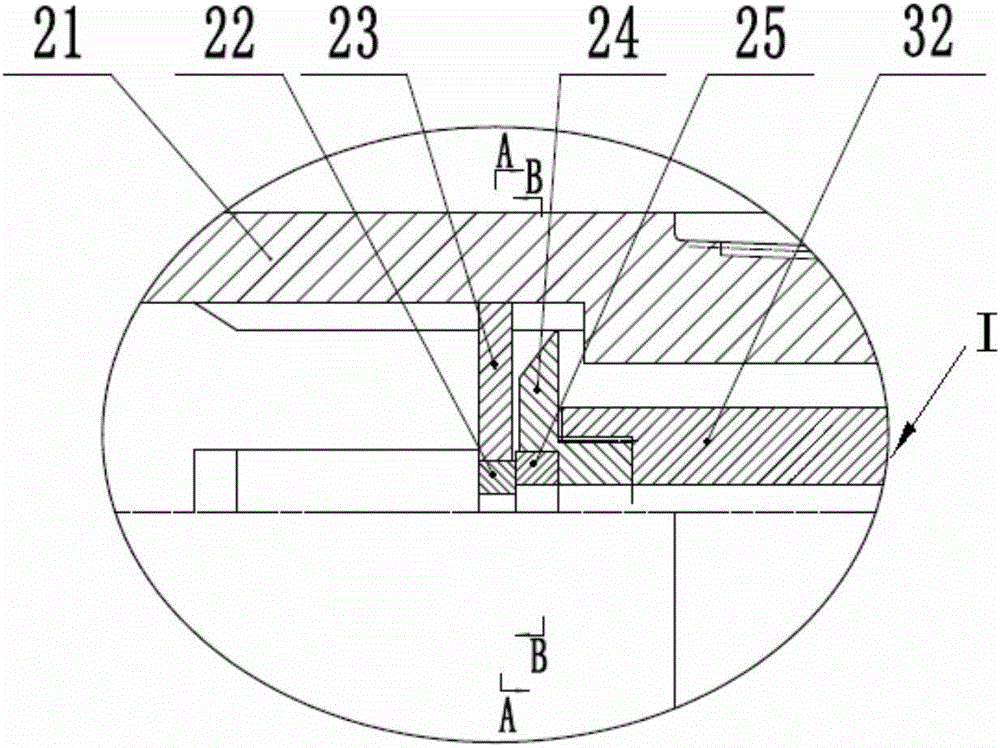
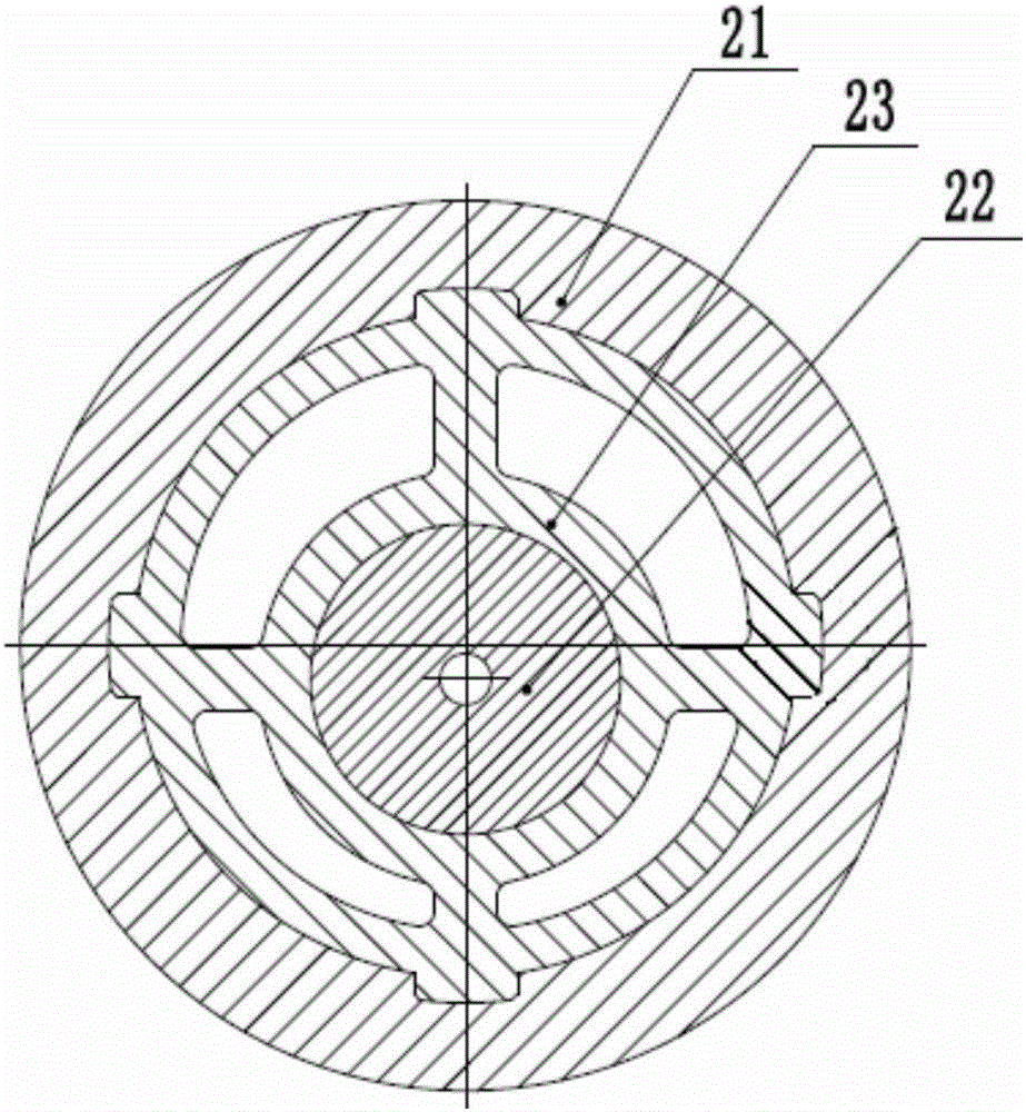
[0023] Such as Figure 1 to Figure 4 As shown, a twisting motor of the present invention includes a bypass valve assembly 1, a motor assembly 3, a cardan shaft assembly 4 and a transmission shaft assembly 5 connected in sequence from left to right, and the bypass valve Assembly 1, motor assembly 3, cardan shaft assembly 4 and transmission shaft assembly 5 are similar in structure to ordinary screw drilling tools. The motor assembly 3 includes a screw stator 31, and the screw stator 31 is provided with a Screw rotor 32 with axial center hole. The transmission shaft assembly 5 includes a lower joint 51 for connecting a drill bit.

[0024] A torque pulse generator 2 is connected between the bypass valve assembly 1 and the motor assembly 3. The torque pulse generator 2 includes a sleeve joint 21, and the left end of the sleeve joint 21 is provided with a bypass valve ass...


PUM


Abstract

The invention discloses a torque pulse motor which comprises a bypass valve assembly, a motor assembly, a universal shaft assembly and a transmission shaft assembly, wherein the bypass valve assembly, the motor assembly, the universal shaft assembly and the transmission shaft assembly are sequentially connected from left to right. The motor assembly comprises a screw rod stator and a screw rod rotor with a central hole. A torque pulse generator is connected between the bypass valve assembly and the motor assembly. The torque pulse generator comprises a sleeve connector, and a stator flow divider valve and a rotor flow divider valve are arranged in the sleeve connector. An upper nozzle is eccentrically arranged in the stator flow divider valve. Axial through holes are formed in the stator flow divider valve along the circumference. The right end of the rotor flow divider valve is connected with the screw rod rotor. A lower nozzle is arranged in the central hole of the rotor flow divider valve, and the axis of a central hole of the lower nozzle is parallel to the axis of a central hole of the upper nozzle. Flow fluctuation is generated by drilling fluid passing through the torque pulse generator, so that the rotating speed of a transmission shaft in the transmission shaft assembly varies, the stick-slipping and vibration phenomena of a PDC drill bit-drill stem in the drilling process are eliminated, the drilling speed is increased, and the service life of a drill bit is prolonged.

Description

technical field [0001] The present invention relates to an auxiliary tool for drilling, and more specifically, relates to a torsion thrust motor. Background technique [0002] At present, ordinary screw drilling tools have been widely used in the oil and natural gas drilling process; the working principle of ordinary screw drilling tools is that the mud pumped by the mud pump flows into the motor through the bypass valve, and a certain gap is formed at the inlet and outlet of the motor. The pressure difference pushes the rotor to rotate around the axis of the stator, and transmits the speed and torque to the drill bit through the cardan shaft and the transmission shaft, so as to realize the drilling operation in which the screw drilling tool converts the hydraulic pressure energy into mechanical energy; but during the drilling operation, It takes a certain amount of energy for the screw drilling tool to drive the drill bit to cut the rock formation. During this process, the ...

Claims


Application Information

Patent Timeline
Patent Type & Authority Applications(China)
IPC IPC(8): E21B4/02
CPCE21B4/02
Inventor 朱益辉刘禹铭李波赵金成冯跃凯吕克华孟凡华王昆剑
Owner CHINA NAT OFFSHORE OIL CORP
Learn More