Diamond compact

A diamond composite sheet and diamond technology, which is applied in the field of diamond composite sheets, can solve the problems of high drilling cutting resistance, high drill bit torque, and low drilling efficiency, so as to increase the ROP, increase the ROP, and reduce the drilling efficiency. The effect of cutting resistance

Inactive Publication Date: 2016-11-09
KINGDREAM PLC CO +1
View PDF8 Cites 9 Cited by
  • Summary
  • Abstract
  • Description
  • Claims
  • Application Information

AI Technical Summary

Problems solved by technology

There are also PCD layers with special-shaped teeth such as spherical head and conical teeth. Although the PDC with this special-shaped structure impro

Method used


Image

  • Diamond compact
  • Diamond compact
  • Diamond compact

Examples


Example Embodiment

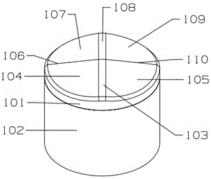
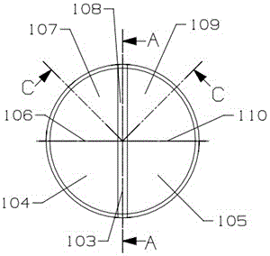
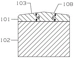
[0026] Example as Figure 1 to Figure 4 As shown, it includes a diamond composite layer 101 and a cemented carbide substrate 102. The end surface of the diamond composite layer has two upwardly protruding band-shaped ridges. Each band-shaped ridge extends upward from the edge of the composite layer and meets at the center of the end surface. The strip-shaped ribs are uniformly distributed along the circumferential direction, that is, the central angle between two adjacent strip-shaped ribs is 180°. One side of the end surface is composed of a band-shaped rib 108 and side wings 107 and 109 on both sides, and the other side of the end surface is composed of a band-shaped rib 103 and the side wings 104 and 105 on both sides. The flanks of the two intersect each other to form lines of intersection 106 and 110. In this embodiment, the angles at which the two band-shaped ribs incline upward, that is, the angles θ and δ between the vertical projection plane of the end face are equal, a...

Example Embodiment

[0027] Example two Figure 5 to Figure 8 As shown, the difference from the first embodiment is that the angles θ and δ at which the two belt-shaped ribs 203, 208 are inclined upward are both 4.5°, and the side wing surfaces 204, 205 ( Or 209, 207) the inclination angles α and β are not equal, the inclination angle α is 5°, and the inclination angle β is 10°. The side wing surface with the larger inclination angle has a larger area, and the corresponding side wing surfaces on both sides intersect in pairs to form a line of intersection 206 , 210.

Example Embodiment

[0028] Example three Figure 9 to Figure 12 As shown, the end face of the diamond composite layer has three upwardly protruding belt-shaped ribs 303, 306, and 308. Each belt-shaped rib extends upward from the edge of the composite layer and meets at the center of the end surface. It is evenly distributed in the circumferential direction, that is, the central angle between two adjacent band-shaped ribs is equal, which is 120°, and the angle θ at which the three band-shaped ribs incline upward is the same, which is 5°. Three side wing surfaces 304, 305, and 307 are arranged corresponding to the three band-shaped ribs, and the inclination angles α, β, and λ of the three side wing surfaces are equal. The other structure is the same as the first embodiment.


PUM

PropertyMeasurementUnit
Widthaaaaaaaaaa

Abstract

The invention relates to a diamond compact which comprises a hard alloy matric and a diamond composite layer. The diamond compact is characterized in that the end face of the diamond composite layer is provided with at least two upward-protruding strip-shaped flanges, and each strip-shaped flange is inclined upwards from the edge of the composite layer and extends and intersects at the middle of the end face. Due to the fact that the multiple strip-shaped flanges are arranged, cutting faces have the strong ploughing effect, the breaking and drilling performance of the compact is improved, the drilling cutting resistance is decreased, and then the mechanical penetration rate of a diamond drill bit is increased; meanwhile, the cutting faces composed of the strip-shaped flanges and the lateral inclined faces also have the impact resistance, the effect of guiding rock debris at the bottom of a well to be discharged can be achieved, and further the mechanical drilling speed of the diamond drill bit is increased; the impact resistance of the compact is further enhanced. The cutting faces of the compact are larger, the abrasion resistance of the compact can be further improved, and therefore the service life of the diamond drill bit can be prolonged.

Description

technical field [0001] The invention relates to a diamond composite sheet, which belongs to the technical field of petroleum drilling. Background technique [0002] Since the 1980s, diamond drill bits have been widely used in oil and gas drilling projects. Diamond drills are mainly composed of drill bodies and cutting elements. Diamond drills are divided into three categories according to cutting elements: PDC (polycrystalline diamond) drills, TSP (thermally stable polycrystalline diamond) drills and natural diamond drills. PDC bits are mainly used for drilling in soft to medium-hard formations. After continuous technological progress, the scope of application of PDC bits is getting wider and wider, and they have better economic value. TSP bits are mainly used for drilling in medium-hard to extremely hard formations. At present, deep well operations in oil and gas drilling projects are gradually increasing, and the formations encountered are becoming more and more complex....

Claims


Application Information

Patent Timeline
IPC IPC(8): E21B10/46
CPCE21B10/46
Inventor 涂关富
Owner KINGDREAM PLC CO
Why Eureka
Try Eureka