Multi-ridge diamond composite sheet

A diamond composite sheet and diamond technology, which is applied in the field of multi-ridge diamond composite sheets, can solve the problems of high drill bit torque, high drilling and cutting resistance, low drilling efficiency, etc. The effect of shock power enhancement

Active Publication Date: 2018-10-16
KINGDREAM PLC CO +1
View PDF4 Cites 8 Cited by
  • Summary
  • Abstract
  • Description
  • Claims
  • Application Information

AI Technical Summary

Problems solved by technology

There are also PCD layers with special-shaped teeth such as spherical head and conical teeth. Although the PDC with this special-shaped structure improves its impact resistance, there are phenomena such as large drilling and cutting resistance, high drill torque, and low drilling efficiency during use.

Method used


Image

  • Multi-ridge diamond composite sheet
  • Multi-ridge diamond composite sheet
  • Multi-ridge diamond composite sheet

Examples


Embodiment 1

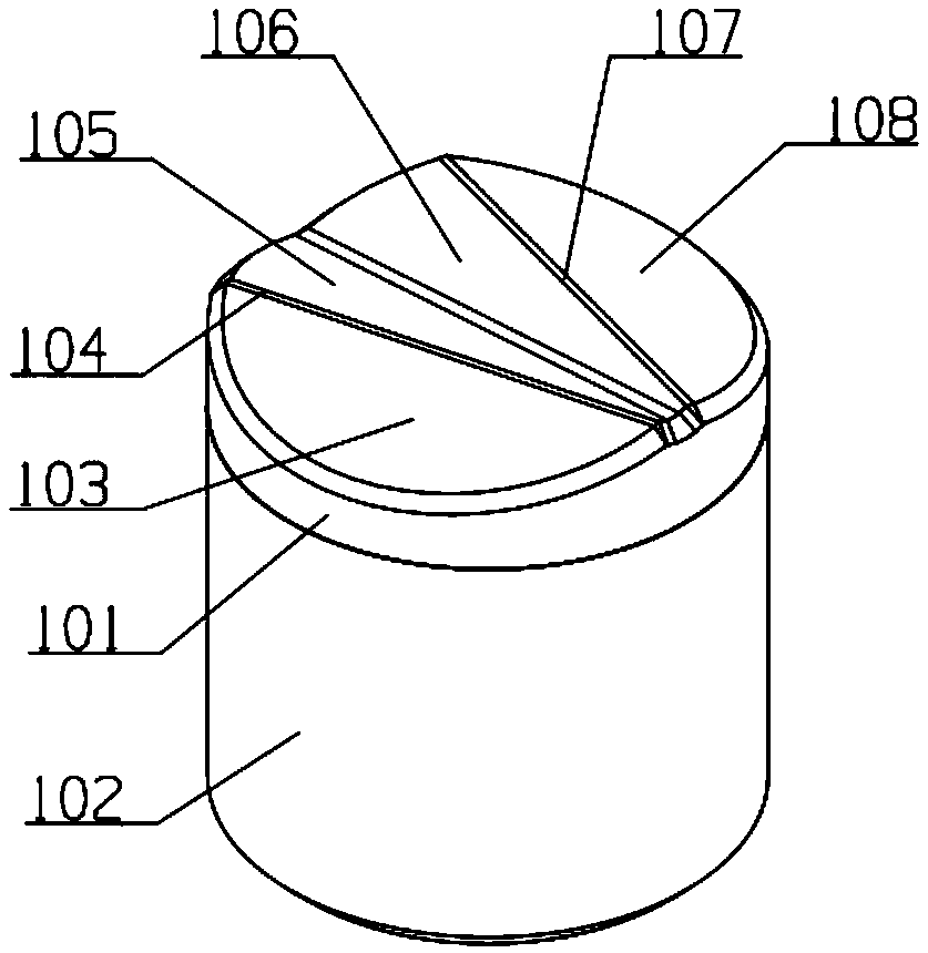
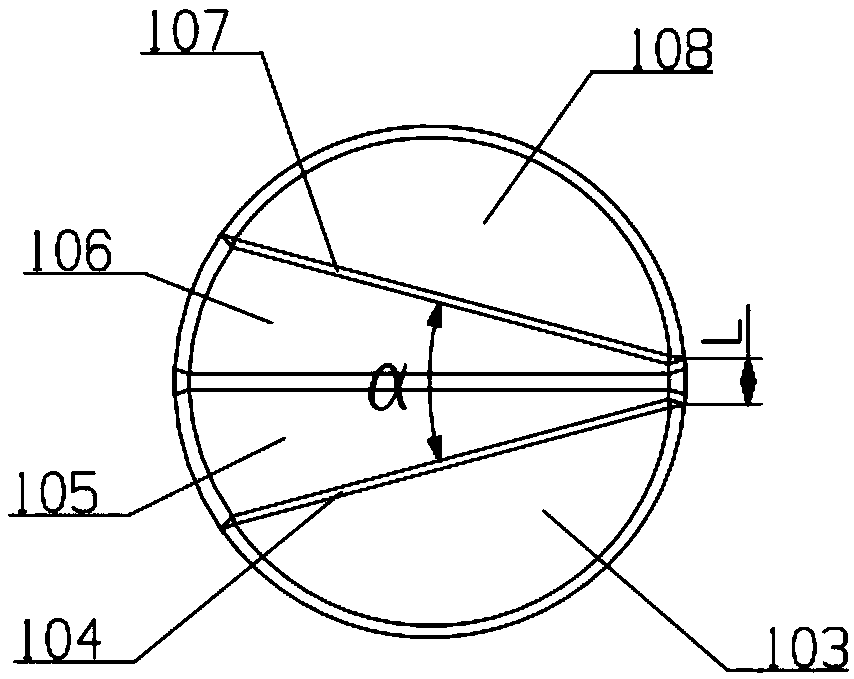
[0031] Example as figure 1 , figure 2 As shown, including a columnar diamond composite layer 101 and a columnar cemented carbide substrate 102, the end face of the diamond composite layer is provided with two ridges (104, 107) at a certain angle, and the contraction ends of the two ridges (104, 107) The extension meets the edge of the diamond composite layer, and the expansion end also extends and meets the edge of the diamond composite layer. The edge of the diamond composite layer is chamfered, so that the edge of the diamond composite layer forms a contracted cone surface, and the intersection of the contracted cone surface and the contracted end of each convex ridge forms a cutting edge. The convex ridge 104 is formed by the intersection of two slopes 103 and 105 , the convex ridge 107 is formed by the intersection of two slopes ( 106 , 108 ), and grooves are provided between adjacent slopes ( 105 , 106 ). In the present embodiment, the radius of the curved surface of t...

Embodiment 2

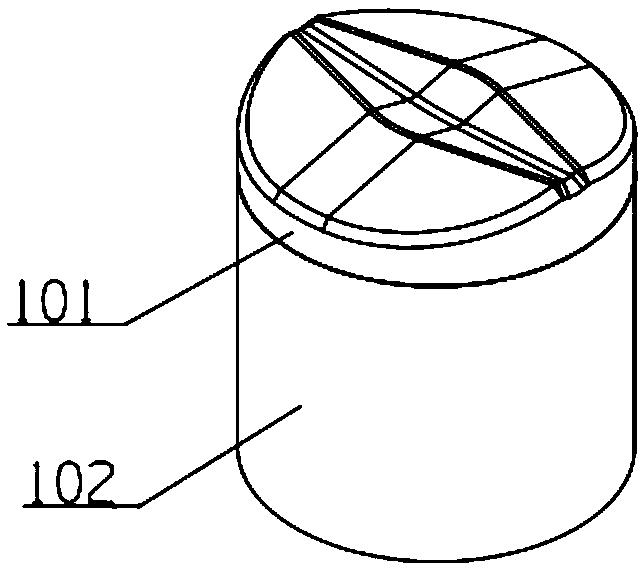
[0033] Example two such as image 3 As shown, the difference from Embodiment 1 lies in that two expanded ends of the convex ridge meet at the end surface of the diamond composite layer, and the meeting place is located at the center of the two, and meets through the transition surface. In addition, this embodiment is provided with two groups of convex ridges arranged symmetrically. Each group of convex ridges is composed of two convex ridges with a certain angle. Meet through transition faces. The constricted ends of the two groups of convex ridges meet with the edges of the diamond composite layer to form two groups of cutting edges (namely two), and the cutting edges are arranged symmetrically at 180°.

Embodiment 3

[0034] Embodiment three such as Figure 4 As shown, it differs from Embodiment 2 in that it is provided with three sets of ridges, and the three sets of ridges are evenly arranged along the circumference of the end face of the diamond composite layer to form three sets of cutting edges, which are distributed at 120°.


PUM

PropertyMeasurementUnit
angleaaaaaaaaaa
angleaaaaaaaaaa
widthaaaaaaaaaa

Abstract

The invention discloses a multi-ridge diamond composite sheet. The multi-ridge diamond composite sheet comprises a cemented carbide matrix and a diamond composite layer. The multi-ridge diamond composite sheet is characterized in that two or more protruding ridges forming a certain included angle are arranged on the end face of the diamond composite layer, and the contracting ends of all the protruding ridges extend to interest at the edge of the diamond composite layer. According to the multi-ridge diamond composite sheet, the multiple protruding ridges forming the certain angle are arrangedto serve as cutting surface sets to simultaneously cut a stratum; the stratum is pre-crushed firstly through the protruding ridges forming the certain angle, sharp surfaces (the contracting ends of the protruding ridges) are inserted into the stratum firstly, a crushed pit is further enlarged in the direction of the ridges, and then the stratum is further extruded and crushed through the bevels ofthe two sides of the set of ridge surfaces, so that the cutting surfaces of the ridges have the high ploughing effect, the crushing drilling performance of the composite sheet is improved, the drilling cutting resistance is decreased, and thus the mechanical drilling speed of a diamond drill bit is increased.

Description

technical field [0001] The invention relates to a multi-ridge diamond composite sheet, which belongs to the technical field of petroleum drilling. Background technique [0002] Since the 1980s, diamond drill bits have been widely used in oil and gas drilling projects. Diamond drills are mainly composed of drill bodies and cutting elements. Diamond drills are divided into three categories according to cutting elements: PDC (polycrystalline diamond) drills, TSP (thermally stable polycrystalline diamond) drills and natural diamond drills. PDC bits are mainly used for drilling in soft to medium-hard formations. After continuous technological progress, the scope of application of PDC bits is getting wider and wider, and they have better economic value. TSP bits are mainly used for drilling in medium-hard to extremely hard formations. At present, deep well operations in oil and gas drilling projects are gradually increasing, and the formations encountered are becoming more and m...

Claims


Application Information

Patent Timeline
Patent Type & Authority Applications(China)
IPC IPC(8): E21B10/46
CPCE21B10/46E21B10/5676E21B10/5673
Inventor 刘强涂关富徐红
Owner KINGDREAM PLC CO
Why Eureka
Try Eureka