Self-lubricating contact device for low-temperature liquid pump and using method of self-lubricating contact device

A low-temperature liquid and contact device technology, which is applied to components of pumping devices for elastic fluids, liquid fuel engines, pump components, etc., can solve problems such as liquid medium vaporization seals, failure, and temperature rise of liquid contact surfaces, and achieve Improve the dynamic pressure effect, reduce frictional heat, and achieve the effect of no leakage

Inactive Publication Date: 2016-11-09
魏宇坤
View PDF9 Cites 0 Cited by
  • Summary
  • Abstract
  • Description
  • Claims
  • Application Information

AI Technical Summary

Problems solved by technology

[0003] The purpose of the present invention is to provide a self-lubricating contact device and method for a low-temperature liquid pump in view of the above-mentioned defects in the prior art, which can solve the problem of excessive temperature rise of the above-mentioned liquid contact end surface and seal failure caused by vaporization of the liquid medium

Method used


Image

  • Self-lubricating contact device for low-temperature liquid pump and using method of self-lubricating contact device
  • Self-lubricating contact device for low-temperature liquid pump and using method of self-lubricating contact device
  • Self-lubricating contact device for low-temperature liquid pump and using method of self-lubricating contact device

Examples


Embodiment 1

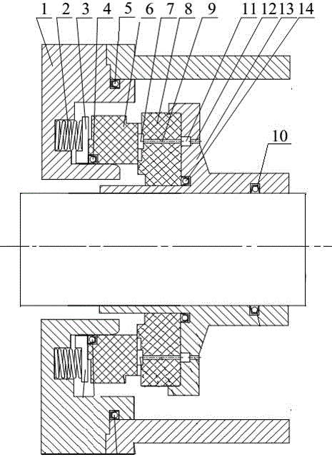
[0021] Embodiment 1, with reference to attached Figure 1-4 , to further describe the present invention:

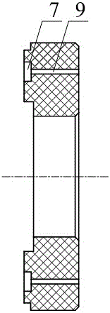
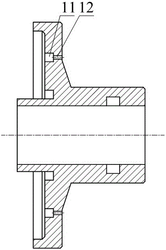
[0022] A self-lubricating contact device for a cryogenic liquid pump mentioned in the present invention includes a gland 1, a spring 2, a push plate 3, a stationary ring 6, a rotating ring 8, and a shaft sleeve 13. A groove is provided on one side of the gland 1, The spring 2 and the push plate 3 are connected to the stationary ring 6, and the push plate 3 enables the stationary ring 6 to have axial compensation capability. The right side of the stationary ring 6 is in contact with the rotating ring 8, and the rotating ring 8 is in contact with the The end face of the stationary ring 6 is provided with an annular groove body 7, and a plurality of drainage channels 9 are arranged inside the annular groove body 7, and concave high-pressure dynamic pressure channels are respectively provided on both sides of the annular groove body 7. The groove 16 and the low-pressure dyna...

Embodiment 2

[0028] Embodiment 2 differs from Embodiment 1 in that the number of low-pressure dynamic pressure grooves is 24; the number of the above-mentioned drainage channels 9 is 24; in addition, refer to the attached Figure 5 , the high-pressure dynamic pressure groove 16 and the low-pressure dynamic pressure groove 17 both adopt a spiral structure, specifically referring to the attached Figure 5 , under the action of viscous shear force, the liquid medium leaked from the drainage channel to the low-pressure side of the seal is returned to the sealed cavity. Function, to achieve no leakage of the sealed liquid medium.

Embodiment 3

[0029] Embodiment 3 differs from Embodiment 1 in that the number of low-pressure dynamic pressure grooves is 16; the number of the above-mentioned drainage channels 9 is 20; in addition, refer to the attached Figure 5 , the high-pressure dynamic pressure groove 16 adopts a spiral structure, the low-pressure dynamic pressure groove 17 adopts a V-shaped structure, and the middle is a ring-shaped groove body. For details, refer to the attached Figure 6 , under the action of viscous shear force, the liquid medium leaked from the drainage channel to the low-pressure side of the seal will be returned to the sealed cavity. The structure makes it disturb the flow and reverse the flow, and can also better eliminate the leakage under the action of the pressure difference, and realize no leakage of the sealed liquid medium.


PUM


Abstract

The invention relates to a self-lubricating contact device for a low-temperature liquid pump and a using method of the self-lubricating contact device. According to the technical scheme adopted by the invention, a pressure cover is connected to a static ring through a pushing plate; the right side of the static ring is in contact fit to a rotary ring; a circular-ring-shaped slot body is formed in the end surface, which is fitted to the static ring, of the rotary ring; a plurality of drainage channels are formed inside the circular-ring-shaped slot body; a sunken high-pressure dynamic pressure slot and a sunken low-pressure dynamic pressure slot are separately formed in the two sides of the circular-ring-shaped slot body; and the circular-ring-shaped slot body communicates with the sunken high-pressure dynamic pressure slot and the sunken low-pressure dynamic pressure slot. The self-lubricating contact device has the beneficial effects that: the drainage channels are rotatably arranged in the rotary ring for directly introducing a sealed medium into the contact end surface in a self-drainage mode; under the fluid static-pressure effect and the guide effect of the circular-ring-shaped slot body, the contact end surface is in a full fluid-film lubrication state, so that friction heat generated by the end surface is greatly reduced; besides, the high-pressure dynamic pressure slot and the low-pressure dynamic pressure slot with V-shaped structures or spiral structures are adopted, no leakage is further ensured, so that stability of a power device is improved.

Description

technical field [0001] The invention relates to a self-lubricating contact device and method, in particular to a low-temperature liquid pump self-lubricating contact device and method. Background technique [0002] The mechanical seal is a device used to solve the dynamic sealing between the rotating shaft and the body. In some special fields, such as liquid rocket engines, cryogenic liquid pumps are used. The general requirements are: the sealing structure is simple and reliable, and no peripherals are required. auxiliary system. For the cryopump in the liquid rocket engine, the leakage of the seal is required to be zero during pre-cooling and filling; when the engine is working, only a small amount of gas and oxygen is allowed to leak from the rear end of the seal; the seal is required to have the ability to start multiple times. The mechanical seal for the cryopump is the key to the long-term safe operation of the cryopump. However, for ordinary mechanical seals, since ...

Claims


Application Information

Patent Timeline
Patent Type & Authority Applications(China)
IPC IPC(8): F04B53/18
CPCF04B53/18
Inventor 不公告发明人
Owner 魏宇坤
Why Eureka
Try Eureka