
Integrated liquid rocket engine high-speed turbo pump rotor dynamic characteristics test device

A turbo pump rotor and liquid rocket technology, which is applied in the direction of measuring devices, testing of mechanical components, testing of machine/structural components, etc., can solve the problem of not being able to guarantee the concentricity of the rotor to drive the motor to the center, and it is difficult to stably increase the speed to a higher speed , interference test data acquisition accuracy and other issues, to achieve the effect of simplifying the number of adapters, good bearing lubrication effect, improving safety and accuracy

Active Publication Date: 2018-05-22
BEIJING AEROSPACE PROPULSION INST
View PDF6 Cites 0 Cited by
  • Summary
  • Abstract
  • Description
  • Claims
  • Application Information

AI Technical Summary

Problems solved by technology

[0003] Existing turbine pump rotor test devices are all split test devices, that is, a support device is designed at the two fulcrums of the rotor respectively. This design cannot guarantee the high concentricity of the rotor and the degree of alignment with the driving motor. , which not only interferes with the accuracy of test data collection, but even causes the motor drive shaft to break
At the same time, due to the split structure, the rigidity of the test device is weak, it is difficult to rise to a high speed stably, and it is easy to resonate with the test rotor, which is extremely dangerous

Method used


Image

  • Integrated liquid rocket engine high-speed turbo pump rotor dynamic characteristics test device
  • Integrated liquid rocket engine high-speed turbo pump rotor dynamic characteristics test device
  • Integrated liquid rocket engine high-speed turbo pump rotor dynamic characteristics test device

Examples


Embodiment Construction

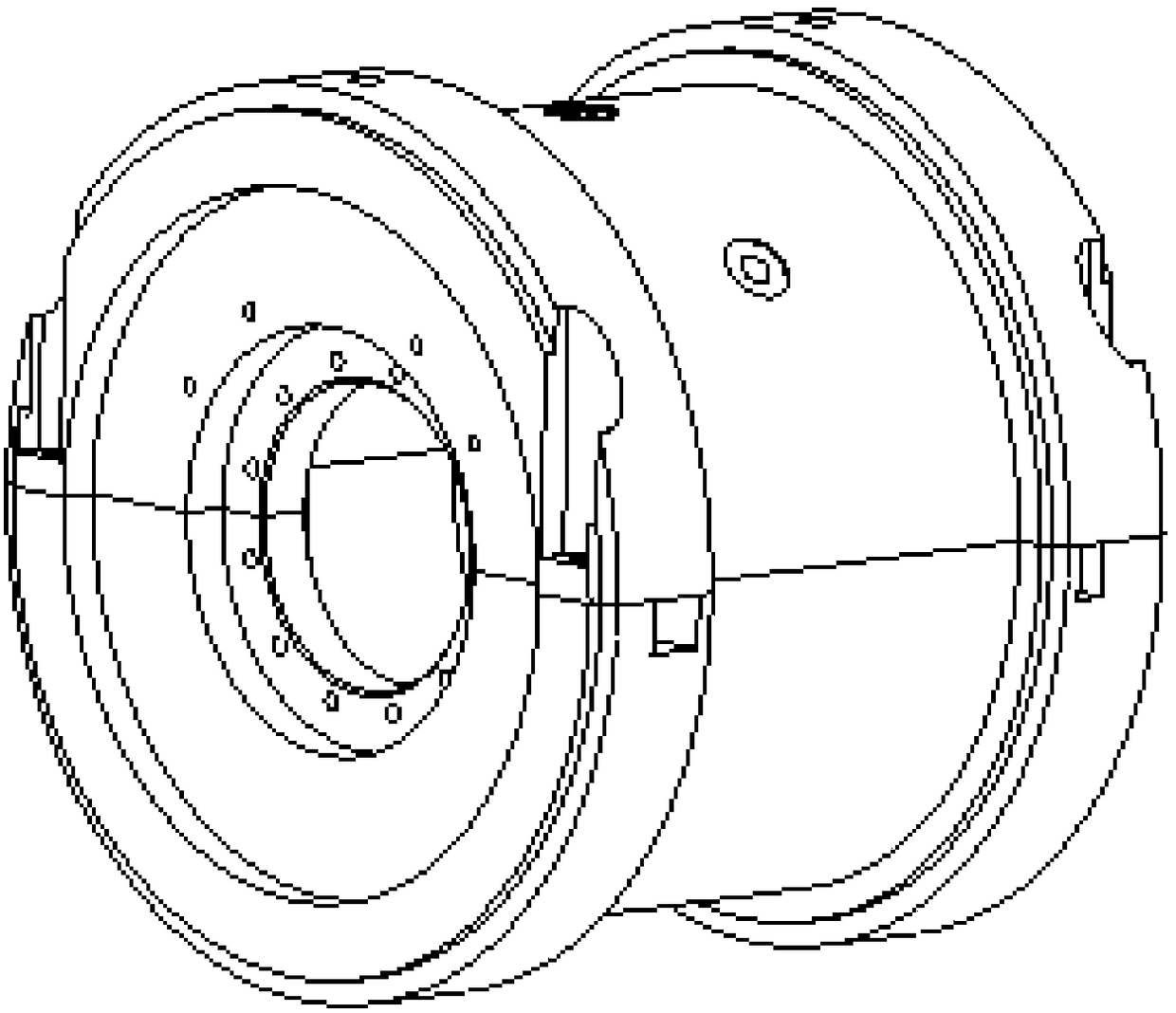
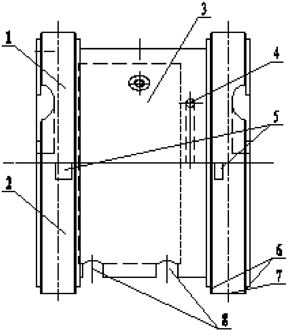
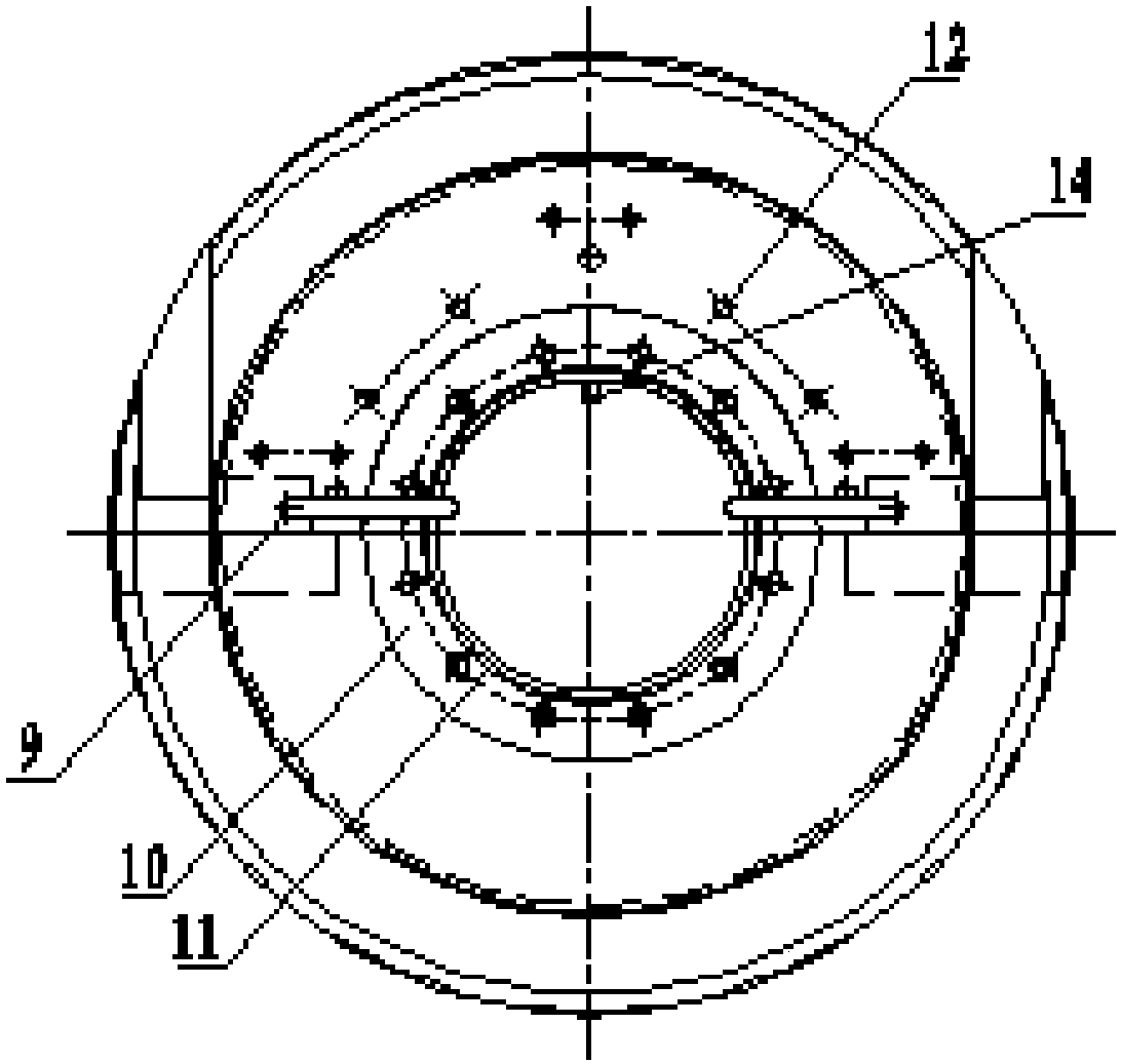
[0029] The basic idea of ​​the present invention is: the integrated liquid rocket engine high-speed turbo pump rotor dynamic characteristic test device is composed of upper and lower tiles. The self-integrated structure consolidates the two support positions into one body, which improves the positioning accuracy and rigidity of the support. The outside of the tile is docked with the test support device through the positioning surfaces on both sides, and positioned by the positioning pin on the top of the upper tile, which can effectively ensure the alignment between the test rotor and the test device. There are 4 oil inlet holes on the side of the lower pad, and the lubricating oil can lubricate the bearing through the built-in oil circuit. The design of the oil circuit ensures the efficient and accurate lubrication of the bearing. The inside of the tile is a hollow oil return chamber, and there are two oil return holes at the bottom of the lower tile to ensure the circulation...


PUM


Abstract

The invention discloses an integrated liquid propellant rocket engine high speed turbo-pump rotor dynamic characteristic testing device. The integrated liquid propellant rocket engine high speed turbo-pump rotor dynamic characteristic testing device comprises a device upper pad (1), a device lower pad (2), a lubricating oil return cavity (3), a bearing intermediate lubricating oil path (4), a lubricating oil inlet(5), a device external axial positioning surface (6), a device external radial positioning surface (7), a lubricating oil return hole (8), bearing two-side lubricating oil injecting pipes (9), a rotor supporting axial positioning surface (10), a rotor supporting radial positioning surface (11), sensor observation points (12), positioning pin holes (13), and bearing intermediate oil injecting pipe (14). Supporting points of two ends of a test piece are connected and supported by an integral tool. The dynamic characteristic testing device provided by the invention is mainly suitable for a turbo-pump rotor system having a small span and a high rotating speed, and at the same time, has a bearing lubricating function, a function of acquiring the arrangement of the observation points, and other functions, and therefore the accuracy and the stability of the dynamic characteristic test of the high speed turbo-pump rotor system are guaranteed.

Description

technical field [0001] The invention discloses an integrated liquid rocket engine high-speed turbo pump rotor dynamic characteristic test device, which relates to the field of liquid rocket engine high-speed turbo pump rotor dynamic characteristic research, and is an integrated device for liquid rocket engine high-speed turbo pump rotor dynamic characteristic test, mainly is a supercritical flexible turbo pump rotor. Background technique [0002] The turbopump rotor system is the main component of the liquid rocket engine turbopump. With the rapid development of the aerospace industry, the performance of the engine continues to improve, and the working speed of the turbopump rotor continues to increase. It is usually a flexible rotor exceeding the first-order or even second-order critical speed. . The flexible rotor has obvious dynamic characteristics under high-speed operation, and is very sensitive to the vibration caused by unbalance and other factors. The study of the v...

Claims


Application Information

Patent Timeline
Patent Type & Authority Patents(China)
IPC IPC(8): G01M13/00
CPCG01M13/00
Inventor 闫宇龙窦唯钱云方刘洋冯楚翔于槟恺
Owner BEIJING AEROSPACE PROPULSION INST
Learn More