Experimental device and method for measuring Young modulus through beam bending method based on simple harmonic oscillation

A simple harmonic vibration and Young's modulus technology, applied in the field of university physics experiments, can solve the problems of wrong data, single principle, inaccurate pulling force, etc. Effect

Inactive Publication Date: 2016-11-09
田凯
View PDF0 Cites 2 Cited by
  • Summary
  • Abstract
  • Description
  • Claims
  • Application Information

AI Technical Summary

Problems solved by technology

[0005] First, the static tensile method is usually used to measure the Young's modulus of metal materials, and the principle is relatively simple
[0006] Second, according to the optical lever amplification principle, the sag of the midpoint of the rectangular cross-section metal beam is measured through the amplification system composed of the optical lever, the telescope and the ruler. Although the method is ingenious, the principle is abstract and difficult to understand, and the adjustment of the telescope is relatively difficult. It is large, and there are many precautions, and it is very easy to get tired and make mistakes in the data, which will affect the accuracy of the measurement results.
[0007] Third, weights are generally used to apply tension to metal beams, and the calculation of tension with the nominal mass of weights is inaccurate, thus affecting the accuracy of experimental results

Method used


Image

  • Experimental device and method for measuring Young modulus through beam bending method based on simple harmonic oscillation
  • Experimental device and method for measuring Young modulus through beam bending method based on simple harmonic oscillation
  • Experimental device and method for measuring Young modulus through beam bending method based on simple harmonic oscillation

Examples


Embodiment Construction

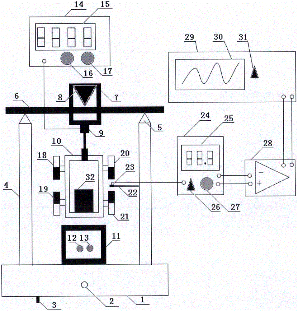
[0039] In the figure, two uprights 4 are set on the base 1, and a steel knife edge is fixed at the upper ends of the two uprights 4, namely the upright knife edge 5. The cutting edges of the two knife edges are parallel to each other, and the two ends of a rectangular cross-section metal beam 6 freely span Set on the knife edges at the upper ends of the two uprights 4, a copper frame 7 is sleeved on the rectangular cross-section metal beam 6. The contact between the copper frame 7 and the rectangular cross-section metal beam 6 is also a knife edge, that is, the copper frame knife edge 8, and the copper frame knife edge 8 Located exactly in the middle of the knife edges at the upper ends of the two uprights, a force-sensitive sensor 9 is provided at the lower end of the copper frame 7. The force-sensitive sensor 9 is connected to a metal frame 10 through a connecting device, and an iron block 32 is fixed inside the metal frame 10, below the metal frame 10 Set up the electromagnet...


PUM


Abstract

The invention discloses an experimental device and method for measuring the Young modulus through a beam bending method based on simple harmonic oscillation, relates to a Young modulus measuring device and method and aims at solving the problems that in current college physical experiments, the experiment principle for measuring the Young modulus through the beam bending method is single and abstract, and the adjustment difficulty of a telescope is high. The device comprises two stand columns arranged on a base, wherein the two ends of a metal beam with a rectangular section are freely arranged on knife edges at the upper ends of the stand columns in a crossover mode, the metal beam is sleeved with a copper frame, a force sensor and a metal frame are arranged at the lower end of the metal beam, an iron block is fixed into the metal frame, an electromagnet device is arranged below the metal beam, and a measuring device is composed of a Hall element, a measurement controller, a Hall voltage amplification device, a digital oscilloscope and the like. According to the method, the cycle of a periodically-changing Hall voltage waveform is measured through the digital oscilloscope, the cycle of simple harmonic oscillation of a spring oscillator of the metal beam is obtained and substituted into a formula, and the Young modulus of a metal material is calculated. The experimental device and method are suitable for measurement of the Young modulus.

Description

Technical field [0001] The invention relates to a college physics experiment, in particular to an experimental device and method for measuring Young's modulus based on the beam bending method of simple harmonic vibration. Background technique [0002] Under the action of external force, the shape change of a solid is called deformation. It can be divided into two types: elastic deformation and normal deformation. The deformation in which the object can completely return to its original shape after the external force is removed is called elastic deformation. If the external force applied to the object is too large, so that after the external force is removed, the object cannot be completely restored to its original state, leaving residual deformation, which is called normal deformation. In this experiment, only elastic deformation is studied. For this reason, the size of the external force should be controlled to ensure that the object can return to its original shape after the...

Claims


Application Information

Patent Timeline
Patent Type & Authority Applications(China)
IPC IPC(8): G01N3/08G01N3/06
CPCG01N3/08G01N3/06G01N2203/0017G01N2203/005
Inventor 田凯董雪峰蔡晓艳贾洁王照平
Owner 田凯
Why Eureka
Try Eureka