Micro-earthquake focus rapid positioning method based on arrival time difference database

A positioning method and database technology, applied in seismology, seismic signal processing, geophysical measurement, etc., can solve problems such as workers and equipment being evacuated too late, loss of life and property, wasting power disaster prediction and early warning time, etc.

Active Publication Date: 2016-11-09
UNIV OF SCI & TECH BEIJING
View PDF5 Cites 33 Cited by
  • Summary
  • Abstract
  • Description
  • Claims
  • Application Information

AI Technical Summary

Problems solved by technology

[0003] In the field of rock mass engineering such as mining and tunneling, due to the suddenness of dynamic disasters such as rock bursts and rockbursts, although there are certain signs before the disaster, the lack of efficient microseismic positioning methods often leads to microseismic monitoring systems. The disaster warning lags behind, and the operators and equipment have no time to evacuate the working face, causing heavy losses to the lives and property of the personnel.
[0004] Most of the traditional microseismic positioning methods involve the optimal value of the iterative solution function. However, in the case of a large amount of data, the iterative process will waste a lot of precious time for dynamic disaster prediction and early warning. direction of efforts

Method used


Image

  • Micro-earthquake focus rapid positioning method based on arrival time difference database
  • Micro-earthquake focus rapid positioning method based on arrival time difference database
  • Micro-earthquake focus rapid positioning method based on arrival time difference database

Examples


Embodiment Construction

[0039] In order to make the technical solutions and advantages of the present invention clearer, the following will describe in detail with reference to the drawings and specific embodiments.

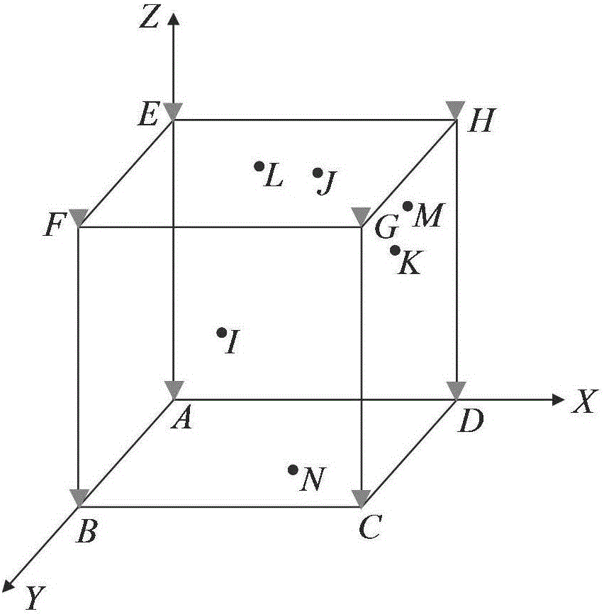
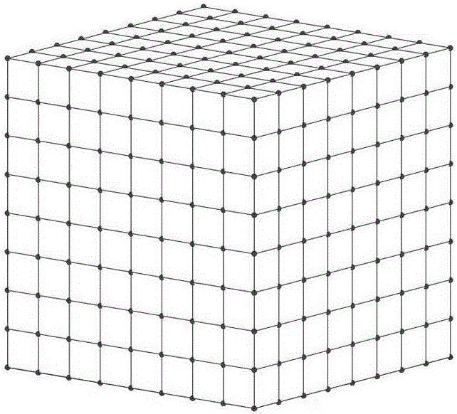
[0040] (1) In order to verify the effectiveness of the present invention, the homogeneous condition is taken as an example, and the solution principle of the heterogeneous condition is the same. A design verification model such as figure 1 As shown, it is a homogeneous model, assuming that there are 8 sensors A, B, C, D, E, F, G, H respectively installed at the eight vertices of the cube, simulating the measured seismic sources I, J, K, L, M , N, O, P position coordinates are shown in Table 1 and Table 2.

[0041] Table 1

[0042] sensor

X / m

Y / m

Z / m

A

0

0

0

B

0

8

0

C

8

8

0

D

8

0

0

E

0

0

8

F

0

8

8

G

8

8

8

H

8

0

8

[0043] Table 2

[0044] ...


PUM


Abstract

The invention provides a micro-earthquake focus rapid positioning method based on an arrival time difference database, and belongs to the earthquake focus positioning technology field. The micro-earthquake focus rapid positioning method comprises the steps that a geological numerical model of a monitoring area is established, and mesh division is carried out, and every mesh point is adopted as a characteristic earthquake focus point; by combining with the characteristic earthquake focus point, a sensor position coordinate, and an earthquake focus wave speed, a characteristic earthquake focus point arrival time difference database is established; by using a waveform information acquisition system, the time of the earthquake source waves arriving at different sensors is extracted from waveform signals received from the sensors; the arrival time difference between any two sensors is calculated, and the arrival time difference matrix of the earthquake focus is established, and the matching searching of the arrival time difference matrix and the characteristic earthquake focus point arrival time difference database is carried out to realize the real-time rapid positioning of the earthquake focus. During an actual micro-earthquake monitoring project, the characteristic earthquake focus point arrival time difference database is established in advance, and the function optimization iteration solution of the earthquake focus is not required, and therefore time required by the earthquake focus positioning is greatly reduced, and rock mass engineering dynamic disaster early warning time is effectively reduced.

Description

technical field [0001] The invention relates to a microseismic source positioning method, in particular to a microseismic source rapid positioning method based on an arrival time difference database. Background technique [0002] In rock mass engineering such as mining and tunneling, mining activities will cause deformation or rupture in local areas of the rock mass, and at the same time, transient elastic waves will be generated with the rapid release of strain energy. This phenomenon is called microseismic. Since microseismic is an accompanying phenomenon of rock mass deformation, crack cracking and expansion process, it is closely related to the mechanical behavior of surrounding rock structure. The useful information of the defect activation process can be used to infer the mechanical behavior of rock materials and predict whether the surrounding rock structure will be damaged. In recent years, the microseismic monitoring technology for real-time monitoring and early wa...

Claims


Application Information

Patent Timeline
Patent Type & Authority Applications(China)
IPC IPC(8): G01V1/28
CPCG01V1/288G01V2210/65
Inventor 吴顺川黄小庆陈子健许学良张诗淮
Owner UNIV OF SCI & TECH BEIJING
Why Eureka
Try Eureka