Single-stage diffraction grating

A diffraction grating and single-order diffraction technology, which is applied in the field of optics, can solve problems such as inaccurate analysis results, reduced spectral accuracy, and errors, and achieve the effects of improving spectral accuracy, improving resolution, and eliminating losses

Active Publication Date: 2016-11-09
INST OF MICROELECTRONICS CHINESE ACAD OF SCI
View PDF4 Cites 10 Cited by
  • Summary
  • Abstract
  • Description
  • Claims
  • Application Information

AI Technical Summary

Problems solved by technology

[0005] Aiming at the problems existing in the prior art, the embodiment of the present invention provides a single-order diffraction grating, which is used to solve the problem that the high-order diffraction and the first-order dif

Method used


Image

  • Single-stage diffraction grating
  • Single-stage diffraction grating
  • Single-stage diffraction grating

Examples


Example Embodiment

[0030] Example one

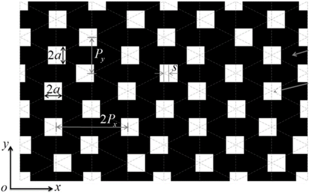
[0031] This embodiment provides a single-order diffraction grating, such as figure 1 As shown, the diffraction grating includes: an opaque film and N light-transmitting holes; wherein, the N light-transmitting holes are distributed on the opaque film in a quasi-triangular grid with a predetermined probability density ; And there is a preset ratio between the size of the light-transmitting hole and the period of the quasi-rhombic grid. Wherein, the oblique square lattice specifically includes: square lattice, rectangular lattice, triangular lattice, centered rectangular lattice and ordinary oblique square lattice. The light-transmitting hole may specifically include a round hole, an elliptical hole or a polygonal hole; the polygonal hole may include a square hole, a symmetrical hexagonal hole, and the like. In this embodiment, the light transmission hole is a square hole, and the oblique square grid is a quasi-triangular grid.

[0032] Specifically, when the N...

Example Embodiment

[0051] Example two

[0052] This embodiment provides a single-order diffraction grating, such as figure 1 As shown, the diffraction grating includes: an opaque film and N light-transmitting holes; wherein, the N light-transmitting holes are distributed on the opaque film in a quasi-triangular grid with a predetermined probability density ; And there is a preset ratio between the size of the light-transmitting hole and the period of the quasi-rhombic grid. Wherein, the oblique square lattice specifically includes: square lattice, rectangular lattice, triangular lattice, centered rectangular lattice and ordinary oblique square lattice. The light-transmitting hole may specifically include a round hole, an elliptical hole or a polygonal hole; the polygonal hole may include a square hole, a symmetrical hexagonal hole, and the like. In this embodiment, the light transmission hole is a square hole, and the oblique square grid is a quasi-triangular grid.

[0053] Specifically, when the N...

Example Embodiment

[0075] Example three

[0076] This embodiment provides a single-order diffraction grating, such as figure 1 As shown, the diffraction grating includes: an opaque film and N light-transmitting holes; wherein, the N light-transmitting holes are distributed on the opaque film in a quasi-triangular grid with a predetermined probability density ; And there is a preset ratio between the size of the light-transmitting hole and the period of the quasi-rhombic grid. Wherein, the oblique square lattice specifically includes: square lattice, rectangular lattice, triangular lattice, centered rectangular lattice and ordinary oblique square lattice. The light-transmitting hole may specifically include a round hole, an elliptical hole or a polygonal hole; the polygonal hole may include a square hole, a symmetrical hexagonal hole, and the like. In this embodiment, the light transmission hole is a square hole, and the oblique square grid is a quasi-triangular grid.

[0077] Specifically, when the...


PUM

PropertyMeasurementUnit
Thicknessaaaaaaaaaa
Thicknessaaaaaaaaaa
Thicknessaaaaaaaaaa

Abstract

The invention provides a single-stage diffraction grating. The diffraction grating comprises an opaque thin film and n light transmitting holes. The n light transmitting holes are distributed on the opaque thin film in the form of quasi-inclined square grids at a preset probability density. The sizes of the light transmitting holes and the period of the quasi-inclined square grids are set according to a preset proportion. In this way, the n light-transmitting holes are distributed on the opaque thin film in the form of quasi-inclined square grids at the preset probability density, so that only the 0-order diffraction and the +/-1-order diffraction are achieved without any high-order diffraction. The harmonic pollution can be eliminated, and the resolution ratio is improved. Furthermore, the accuracy of the analysis result is ensured and the shot spectrum precision is improved. Moreover, the optical grating can realize the self-supporting function, so that the loss caused by a substrate can be eliminated. In addition, since the structure of the grating is only provided with a light-transmitting part and an opaque part, so that the binary structure is easy to machine.

Description

technical field [0001] The invention belongs to the field of optical technology, in particular to a single-stage diffraction grating. Background technique [0002] As we all know, almost all materials and even air can absorb extreme ultraviolet light from 10 nanometers to 121 nanometers, referred to as extreme ultraviolet light. Therefore, in this wavelength band, general lens optical systems cannot be used for beam control, but diffraction gratings and reflectors are used. mirrors for beam control of extreme ultraviolet light. [0003] At present, the extreme ultraviolet spectroscopic system mainly uses diffraction gratings for spectroscopic splitting. The traditional binary grating contains multi-level diffraction. Usually, only the first-order diffraction is needed for light splitting. However, in the case of wide spectrum, the high-order diffraction and the first-order diffraction overlap, which disturbs the analysis results and brings errors that are not easy to elimin...

Claims


Application Information

Patent Timeline
IPC IPC(8): G02B5/18
CPCG02B5/18
Inventor 史丽娜刘子维浦探超李海亮牛洁斌谢常青刘明
Owner INST OF MICROELECTRONICS CHINESE ACAD OF SCI
Why Eureka
Try Eureka