a transmission grating

A transmission grating and light-transmitting film technology, applied in the optical field, can solve problems such as inaccurate analysis results, reduced spectral accuracy, and errors, and achieve the effects of improving spectral accuracy, improving signal-to-noise ratio, and eliminating losses

Active Publication Date: 2019-10-29
INST OF MICROELECTRONICS CHINESE ACAD OF SCI
View PDF4 Cites 0 Cited by
  • Summary
  • Abstract
  • Description
  • Claims
  • Application Information

AI Technical Summary

Problems solved by technology

[0005] Aiming at the problems existing in the prior art, the embodiment of the present invention provides a transmission grating, which is used to solve the problem that in the prior art, when the extreme extreme ultraviolet light splitting system performs light splitting, the high-order diffraction and the first-order diffraction overlap and cause errors. , leading to inaccurate analysis results and technical problems of reduced spectral accuracy

Method used


Image

  • a transmission grating
  • a transmission grating
  • a transmission grating

Examples


Embodiment 1

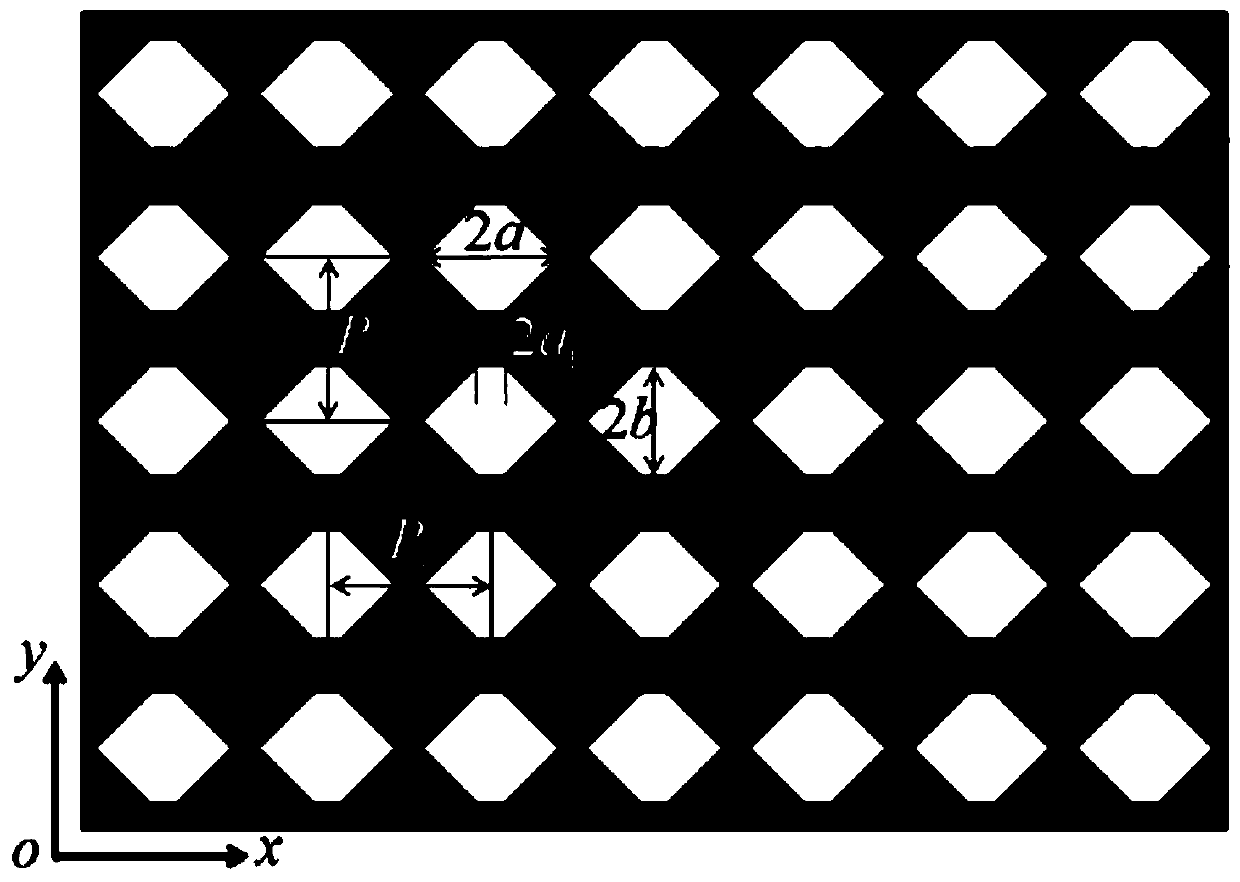
[0029] This embodiment provides a transmission grating, such as figure 1 As shown, the transmission grating includes: an opaque film and N transparent symmetrical polygonal holes; wherein, the N transparent symmetrical polygonal holes are distributed in an oblique grid on the opaque film, and the There is a preset ratio between the period of the rhombic grid and the size of the symmetrical polygonal hole. Wherein, the rhombic lattice specifically includes: square lattice, rectangular lattice, triangular lattice, rectangular lattice with a heart and common oblique lattice. In this embodiment, it is preferably a rectangular grid.

[0030] Specifically, the rectangular grid distribution is specifically: the symmetry center of any symmetrical polygonal hole is connected with the symmetry centers of three adjacent symmetrical polygons to form a rectangle. The period of the rectangular grid along the x-axis direction is P x , that is, the distance between the centers of symmetry ...

Embodiment 2

[0045] Compared with Embodiment 1, this embodiment also provides a transmission grating, which includes: an opaque film and N transparent symmetrical polygonal holes; wherein, the N transparent symmetrical polygonal holes are in the non-transparent The light-transmitting film is distributed with rhombic grids, and there is a preset ratio between the period of the rhomboid grids and the size of the symmetrical polygonal holes. Wherein, the rhombic lattice specifically includes: square lattice, rectangular lattice, triangular lattice, rectangular lattice with a heart and common oblique lattice. In this embodiment, it is preferably a rectangular grid.

[0046] Specifically, the rectangular grid distribution is specifically: the symmetry center of any symmetrical polygonal hole is connected with the symmetry centers of three adjacent symmetrical polygons to form a rectangle. The period of the rectangular grid along the x-axis direction is P x , that is, the distance between the ...

Embodiment 3

[0065] Compared with Embodiment 2, this embodiment also provides a transmission grating, which includes: an opaque film and N transparent symmetrical polygonal holes; The light-transmitting film is distributed with rhombic grids, and there is a preset ratio between the period of the rhomboid grids and the size of the symmetrical polygonal holes. Wherein, the rhombic lattice specifically includes: square lattice, rectangular lattice, triangular lattice, rectangular lattice with a heart and common oblique lattice. In this embodiment, it is preferably a rectangular grid.

[0066] Specifically, the rectangular grid distribution is specifically: the symmetry center of any symmetrical polygonal hole is connected with the symmetry centers of three adjacent symmetrical polygons to form a rectangle. The period of the rectangular grid along the x-axis direction is P x , that is, the distance between the centers of symmetry of adjacent symmetrical polygonal holes along the x-axis direc...


PUM


Abstract

The invention provides a transmission grating. The transmission grating comprises a lightproof film and N light-transmission symmetrical polygonal holes, wherein the N light-transmission symmetrical polygonal holes are distributed on the lightproof film in an inclined square lattice manner, and a preset proportion exists between the period of the inclined square lattices and the sizes of the symmetrical polygonal holes. In this way, the N light-transmission symmetrical polygonal holes are distributed on the lightproof film in the inclined square lattice manner, the background noise is totally inhibited, and the signal to noise ratio is improved. The period of the inclined square lattices and the sizes of the symmetrical polygonal holes are set according to the preset proportion, so that the grating can totally inhibit 2-level, 3-level and 4-level diffraction, the harmonic pollution is eliminated, the resolution is improved, the accuracy of the analysis result is further ensured, and the spectrography precision is improved. In addition, the grating is capable of realizing self supporting, so that the loss caused by a lining is eliminated. And, the grating structure only has light-transmission and lightproof areas, and the binary structure is easy to machine.

Description

technical field [0001] The invention belongs to the field of optical technology, in particular to a transmission grating. Background technique [0002] As we all know, almost all materials and even air can absorb extreme ultraviolet light from 10 nanometers to 121 nanometers, referred to as extreme ultraviolet light. Therefore, in this band, it is impossible to use a general lens optical system to control the beam, but to use diffraction gratings and mirrors. To achieve beam control of extreme ultraviolet light. [0003] At present, the extreme ultraviolet spectroscopic system mainly uses diffraction gratings for spectroscopic splitting. The traditional binary grating contains multi-level diffraction. Usually, only the first-order diffraction is needed for light splitting. However, in the case of wide spectrum, the high-order diffraction and the first-order diffraction overlap, which disturbs the analysis results and brings errors that are not easy to eliminate. spectrosco...

Claims


Application Information

Patent Timeline
Patent Type & Authority Patents(China)
IPC IPC(8): G02B5/18
CPCG02B5/1838G02B5/1866G02B2005/1804
Inventor 史丽娜刘子维浦探超李海亮牛洁斌谢常青刘明
Owner INST OF MICROELECTRONICS CHINESE ACAD OF SCI
Why Eureka
Try Eureka