
Back-contact solar battery and manufacturing method thereof

A solar cell and back-contact technology, applied in the field of solar cells, can solve problems such as difficulty in popularization, incompatibility, and environmental pollution by waste, and achieve simple, reasonable, safe and reliable processes, improve fill factor and short-circuit current, and eliminate current-carrying Effects of sub-transverse transmission losses and electrode shadowing effects

Inactive Publication Date: 2014-04-30
JA SOLAR TECH YANGZHOU +1
View PDF3 Cites 12 Cited by
  • Summary
  • Abstract
  • Description
  • Claims
  • Application Information

AI Technical Summary

Problems solved by technology

In the previous manufacturing process of back-contact solar cells, most of the metallization process is realized by electroplating with a relatively complicated process. Complex, the discharged waste seriously pollutes the environment, and is incompatible with the mainstream metallization method of industrial production, so it is difficult to promote low-cost industrialization

Method used


Image

  • Back-contact solar battery and manufacturing method thereof
  • Back-contact solar battery and manufacturing method thereof
  • Back-contact solar battery and manufacturing method thereof

Examples


Embodiment 1

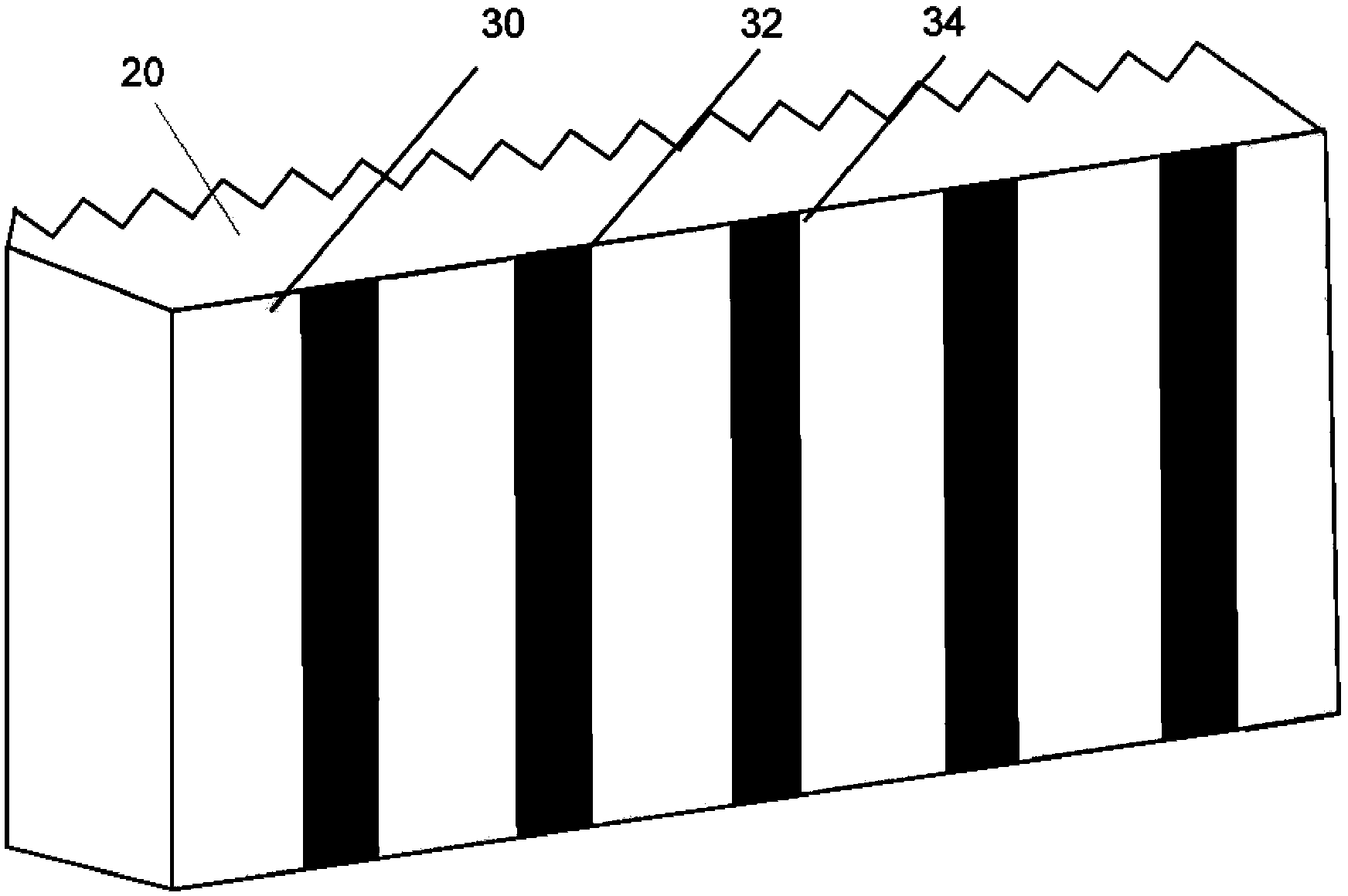
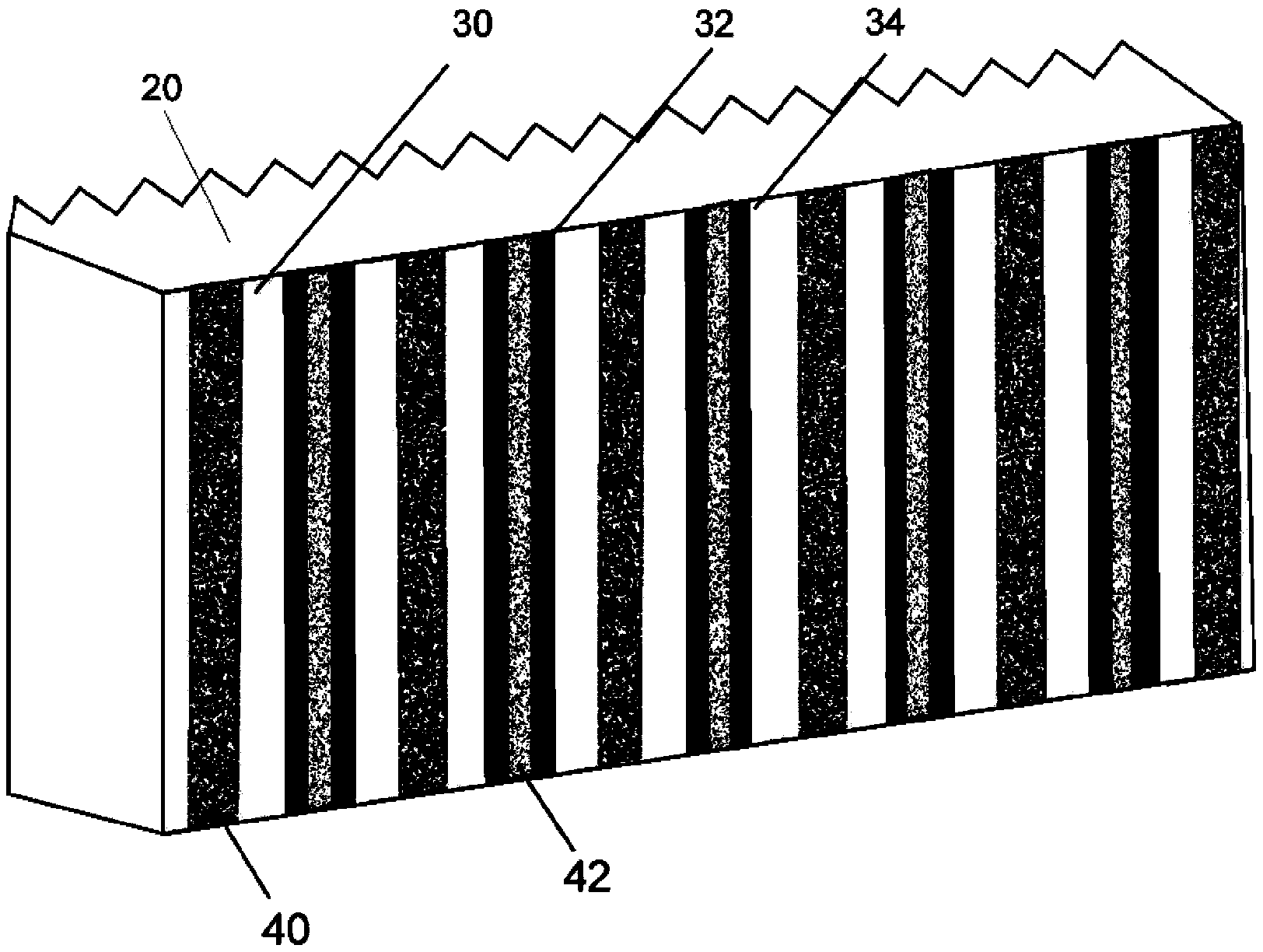
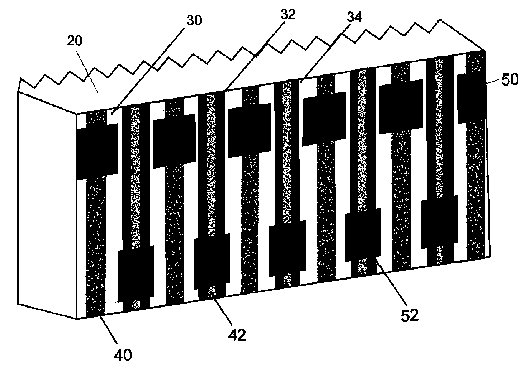
[0037] Such as Figure 4 As shown in , the back contact solar cell provided by this embodiment includes an N-type single crystal silicon substrate silicon substrate 20, a p+ doped region 30 and an n+ doped region 32 arranged on the back side of the silicon substrate, and a p+ doped region 30 and an n+ doped region. The doped regions 32 are alternately arranged on the back side of the silicon substrate 20, the p+ doped region 30 is provided with a positive electrode contact fine grid 40, and the n+ doped region 32 is provided with a negative electrode contact fine grid 42, and on the back side of the silicon substrate 20 A positive electrode main grid 60 and a negative electrode main grid 62 are also provided. An insulating barrier layer 50 is provided at the contact position between the positive electrode main grid 60 and the negative electrode contact fine grid 42 and the n+ doped region 32 where it is located. The grid 60 is located on the insulating barrier layer 50 and is ...


PUM


Abstract

The invention discloses a back-contact solar battery. The back-contact solar battery comprises a silicon substrate, wherein p+ doping areas and n+ doping areas are mutually alternately distributed on the back surface of the silicon substrate, each p+ doping area is provided with a positive-electrode contact fine grid, each n+ doping area is provided with a negative-electrode contact fine grid, the back surface of the silicon substrate is further provided with a positive-electrode main grid and a negative-electrode main grid, the positions, making contact with the negative-electrode contact fine grids, of the positive-electrode main grid are provided with insulation blocking layers, and the positive-electrode main grid is located on the insulation blocking layers and connected with the positive-electrode contact fine grids. The positions, making contact with the positive-electrode contact fine grids, of the negative-electrode main grid are provided with insulation blocking layers, and the negative-electrode main grid is located on the insulation blocking layers and connected with the negative-electrode contact fine grids. The invention further discloses a manufacturing method of the back-contact solar battery. The back-contact solar battery can eliminate carrier transverse transmission loss caused by a common main grid of a back-contact solar battery in the prior art and the electrode shadowing effect of the common main grid, and the number of fill factors and the number of short-circuit currents of the back-contact solar battery are increased.

Description

technical field [0001] The invention belongs to the field of solar cells, and in particular relates to a back contact solar cell and a preparation method thereof. Background technique [0002] A solar cell is a semiconductor device that converts light energy into electrical energy. Lower production costs and higher energy conversion efficiency have always been the goals pursued by the solar cell industry. For conventional solar cells at present, the positive electrode contact electrode and the negative electrode contact electrode are respectively located on the front and back sides of the battery sheet. The front of the battery is the light-receiving surface, and the coverage of the metal positive electrode on the front will inevitably cause a part of the incident sunlight to be reflected by the metal electrode, resulting in a part of optical loss. The coverage area of ​​the front metal electrode of an ordinary crystalline silicon solar cell is about 7%, and reducing the fr...

Claims


Application Information

Patent Timeline
Patent Type & Authority Applications(China)
IPC IPC(8): H01L31/0224H01L31/18
CPCH01L31/022441Y02E10/50Y02P70/50
Inventor 刘志锋尹海鹏张峰汤昆单伟
Owner JA SOLAR TECH YANGZHOU
Learn More