Isolated DC transducer of side edge clamp

A technology of DC converter and isolation transformer, which is applied in the direction of converting DC power input to DC power output, output power conversion equipment, and conversion equipment with intermediate conversion to AC, which can solve the problems of clamping diode damage and easy direct connection. , to achieve the effect of eliminating loss, eliminating influence, eliminating voltage oscillation and voltage spike

Inactive Publication Date: 2007-07-25
NANJING UNIV OF AERONAUTICS & ASTRONAUTICS
View PDF0 Cites 11 Cited by
  • Summary
  • Abstract
  • Description
  • Claims
  • Application Information

AI Technical Summary

Problems solved by technology

The two clamping diodes are turned on alternately in one switching cycle. If the clamping diodes are not turned off fast enough, it is easy to pass through and cause damage to the clamping diodes.

Method used


Image

  • Isolated DC transducer of side edge clamp
  • Isolated DC transducer of side edge clamp
  • Isolated DC transducer of side edge clamp

Examples


Embodiment Construction

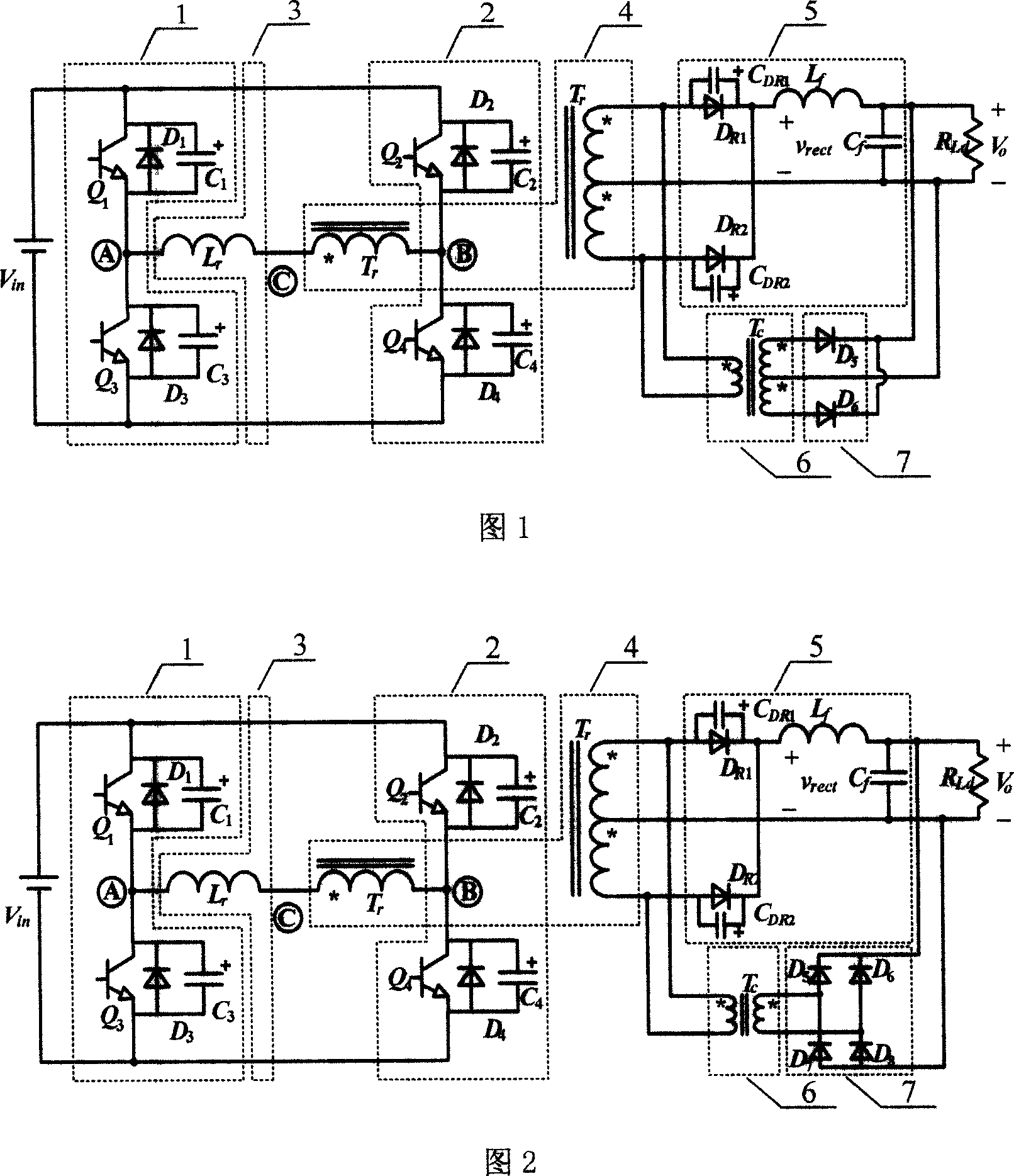
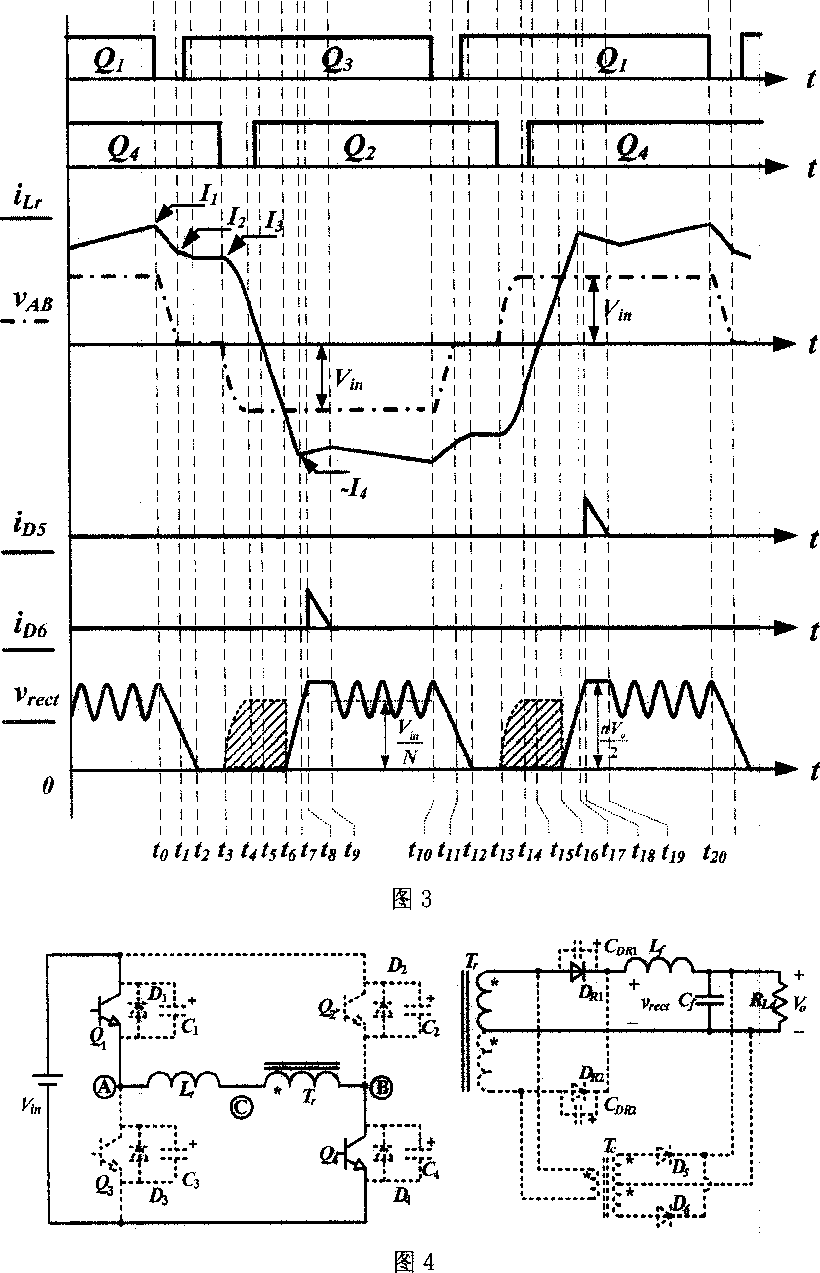
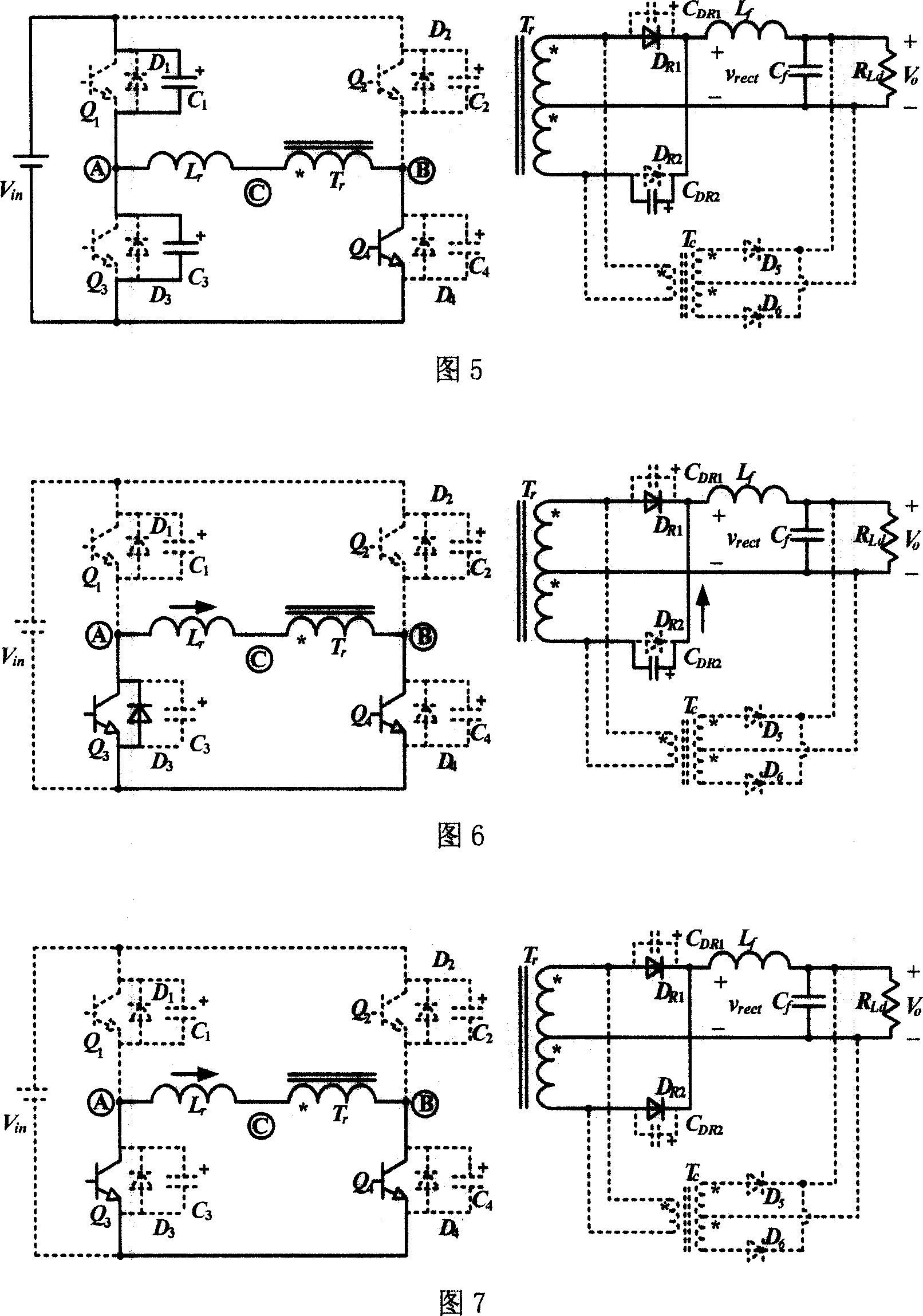
[0010] Figure 1 and Figure 2 show two schematic diagrams of the circuit structure of the isolated DC converter with secondary side clamping. by the DC power supply V in , Two inverter bridge arms 1 and 2, a resonant inductor 3, an isolation transformer 4, a rectification and filter circuit 5, a current transformer 6, and a clamping circuit 7. Q 1 ~Q 4 are four main switch tubes, D 1 ~D 4 are the switching tube Q 1 ~Q 4 body diode, C 1 ~C 4 are the switching tube Q 1 ~Q 4 The parasitic capacitance, L r is the resonant inductance, T r is the isolation transformer, D R1 and D R2 is the output rectifier diode, C DR1 and C DR2 For the output rectifier diode D R1 、D R2 The junction capacitance, L f is the output filter inductor, C f is the output filter capacitor, R Ld is the load, T c is the current transformer, D 5 ~D 8 is the clamping diode. The converter adopts phase-shift control, the switch tube Q 1 and Q 3 Respectively ahead of the switching tube Q ...


PUM


Abstract

The DC convertor is composed of DC power supply, first inversion bridge arm, second bridge arm, resonant inductance, isolating transformer, rectifying and filtering circuit, current transformer, and clipper circuit. The added current transformer and clipper circuit eliminates voltage surge and voltage pike caused by backward recovery of rectifying tube, reduces voltage stress of rectifying tube, and eliminates waste caused by backward recovery of rectifying tube. Since voltage stress of clamp diode is smaller, tube with good capability can be selected to eliminate influence on circuit caused by stray parameter of clamp diode. Moreover, Comparing with mode that a clamp diode is placed at primary side of transformer to clip voltage at primary side, the clipper circuit clips voltage at secondary side of transformer in the invention can eliminate voltage surge and voltage pike of rectifier diode caused by leakage inductance of transformer.

Description

1. Technical field [0001] The isolated DC converter with secondary side clamping of the present invention belongs to the DC converter of an electric energy conversion device. 2. Background technology [0002] In medium and high power DC conversion occasions, the full bridge converter has been widely used because the switching tube is easy to realize soft switching and adopts constant frequency control. In the past two decades, there have been many soft-switching control strategies and circuit topologies for full-bridge converters. Both the phase-shift control zero-voltage switching full-bridge converter and the phase-shift control zero-voltage zero-current switching full-bridge converter can realize the soft switching of the switching tube. However, whether it is a zero-voltage switching or zero-voltage zero-current switching full-bridge converter, due to the reverse recovery of the secondary rectifier diode, the leakage inductance of the transformer (or the additional reso...

Claims


Application Information

Patent Timeline
Patent Type & Authority Applications(China)
IPC IPC(8): H02M3/28H02M3/335H02M7/5387
Inventor 陈乾宏殷兰兰陈乾伟
Owner NANJING UNIV OF AERONAUTICS & ASTRONAUTICS
Why Eureka
Try Eureka