An extreme ultraviolet single-stage diffraction grating

A single-order diffraction and extreme ultraviolet technology, applied in the field of micro-nano optics, can solve problems such as errors, reduced spectral accuracy, and inaccurate analysis results, and achieve the effects of reducing errors, improving signal-to-noise ratio, and improving spectral accuracy

Active Publication Date: 2019-05-21
INST OF MICROELECTRONICS CHINESE ACAD OF SCI
View PDF4 Cites 0 Cited by
  • Summary
  • Abstract
  • Description
  • Claims
  • Application Information

AI Technical Summary

Problems solved by technology

[0006] In view of this, the present invention provides an extreme ultraviolet monopole diffraction grating to solve the technical problems in the prior art that the order superposition of advanced diffraction and first-order diffraction will cause errors, resulting in inaccurate analysis results and reduced spectral accuracy.

Method used


Image

  • An extreme ultraviolet single-stage diffraction grating
  • An extreme ultraviolet single-stage diffraction grating
  • An extreme ultraviolet single-stage diffraction grating

Examples


Embodiment 1

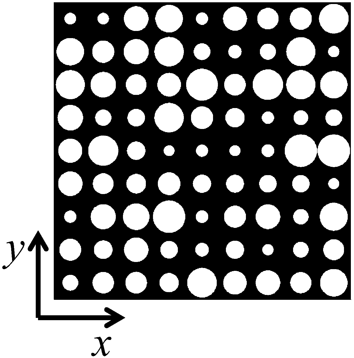
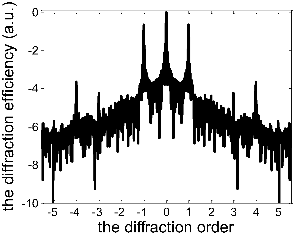
[0031] This embodiment provides an EUV single-stage diffraction grating, comprising: a light-transmitting substrate; an opaque film positioned on the light-transmitting substrate; holes; wherein, the circular light-transmitting through-holes are arranged on the opaque film in a periodic orthorhombic lattice distribution, the center of the circular light-transmitting through-holes is located at the center of the rhomboidal lattice, and the The radius of the circular light-transmitting hole is randomly distributed, and there is a maximum value R max and minimum R min ; In the plane where the opaque film is located, along the first direction, the period of the oblique grid is P x , along the second direction, the period of the orthorhombic lattice is P y , the first direction is perpendicular to the second direction; there is a preset ratio between the period of the rhombic lattice and the maximum and minimum radii of the circular light-transmitting holes.

[0032] See figure...

Embodiment 2

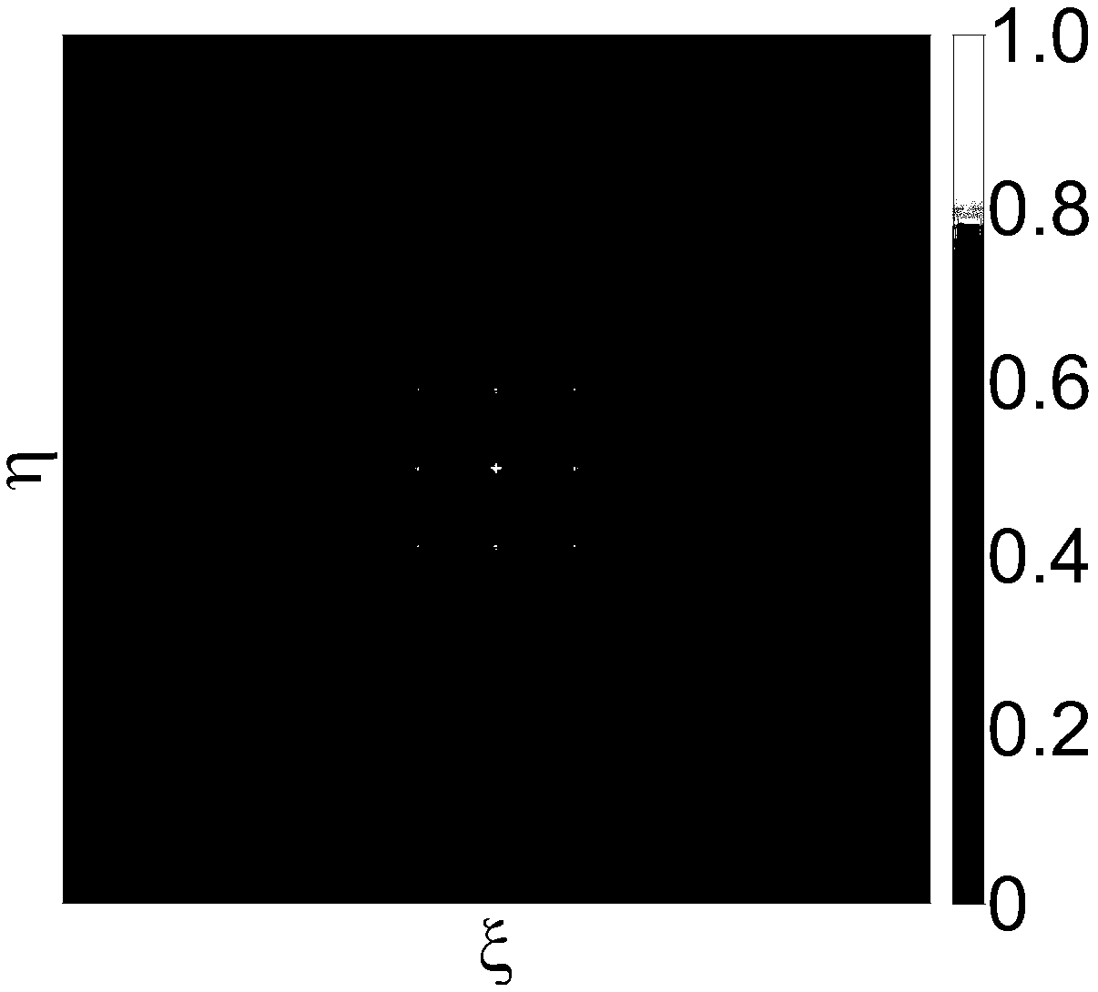
[0041] This embodiment provides an EUV single-stage diffraction grating, comprising: a light-transmitting substrate; an opaque film positioned on the light-transmitting substrate; holes; wherein, the circular light-transmitting through-holes are arranged on the opaque film in a periodic orthorhombic lattice distribution, the center of the circular light-transmitting through-holes is located at the center of the rhomboidal lattice, and the The radius of the circular light-transmitting hole is randomly distributed, and there is a maximum value R max and minimum R min ; In the plane where the opaque film is located, along the first direction, the period of the oblique grid is P x , along the second direction, the period of the orthorhombic lattice is P y , the first direction is perpendicular to the second direction; there is a preset ratio between the period of the rhombic lattice and the maximum and minimum radii of the circular light-transmitting holes.

[0042] See Figur...


PUM


Abstract

The invention provides an extreme ultraviolet single-grade diffraction grating. The extreme ultraviolet single-grade diffraction grating comprises a light transmission substrate and a light-proof thin film which is located on the light transmission substrate, wherein the light-proof thin film is provided with a plurality of round light transmission through holes; the round light transmission through holes with random radiuses are distributed on the light-proof thin film in an inclined square shape, so that background noises are completely inhibited and the signal-to-noise ratio is improved; and the period of inclined squares is assigned according to a pre-set ratio between the maximum value and minimum value of the radius of each round through hole. The grating inhibits + / -2-grade and + / -3grade diffraction, so that harmonic pollution is eliminated, the resolution ratio is improved, and errors of results are greatly reduced; and furthermore, the reliability and accuracy of analysis results are improved, and the spectrographic precision is improved.

Description

[0001] This application claims the priority of the domestic application submitted to the China Patent Office on March 15, 2017, with the application number 201710154230.7 and the title of the invention "An Extreme Ultraviolet Single-Stage Diffraction Grating", the entire content of which is incorporated in this application by reference . technical field [0002] The invention relates to the field of micro-nano optics technology, in particular to an extreme ultraviolet monopole diffraction grating. Background technique [0003] The diffraction grating is the core optical component of the spectrometer, which determines the dispersion and imaging capabilities of the spectrometer. For the role of the diffraction grating in promoting the development of science and technology, in the past ten years, with the development of micro-nano processing technology, people have produced various Type of high-quality diffraction grating; Maxwell's equations can be accurately solved by various...

Claims


Application Information

Patent Timeline
Patent Type & Authority Patents(China)
IPC IPC(8): G02B5/18
CPCG02B5/1838G02B5/1866G02B2005/1804
Inventor 浦探超刘子维史丽娜谢常青李海亮牛洁斌刘明
Owner INST OF MICROELECTRONICS CHINESE ACAD OF SCI
Why Eureka
Try Eureka