Pressure sensor and pressure touch panel

A pressure sensor and touch panel technology, applied in the direction of instrument, electrical digital data processing, data processing input/output process, etc. Control experience effect, uniform response sensitivity, uniform sensing sensitivity effect

Inactive Publication Date: 2016-11-09
WUHAN CHINA STAR OPTOELECTRONICS TECH CO LTD
View PDF5 Cites 9 Cited by
  • Summary
  • Abstract
  • Description
  • Claims
  • Application Information

AI Technical Summary

Problems solved by technology

[0003] The Force Touch panel is mainly based on the deformation generated by the user's finger pressing the surface of the touch panel of the smart electronic product, and uses the Force Sensor to sense the magnitude of the pressure change, thereby realizing the force touch sensing; according to the pressure Different sensing principles, pressure touch panels can be mainly divided into three categories: piezoelectric, piezoresistive, and capacitive; piezoresistive touch panels are simple in design and lowest in cost, but due to Physical limitations, such as low light transmittance, large detection area with high line count cause the burden on the processor of smart electronic products, and the piezoresistive touch panel needs to be kept powered on, which increases the power consumption of electronic products and also makes the It is easy to age and affect the service life, so it is gradually eliminated; the piezoelectric touch panel is driven by voltage to complete the touch. Disadvantages, the production process is not mature enough, and it has not been widely used

Method used


Image

  • Pressure sensor and pressure touch panel
  • Pressure sensor and pressure touch panel
  • Pressure sensor and pressure touch panel

Examples


Embodiment Construction

[0030] In order to further illustrate the technical means adopted by the present invention and its effects, the following describes in detail in conjunction with preferred embodiments of the present invention and accompanying drawings.

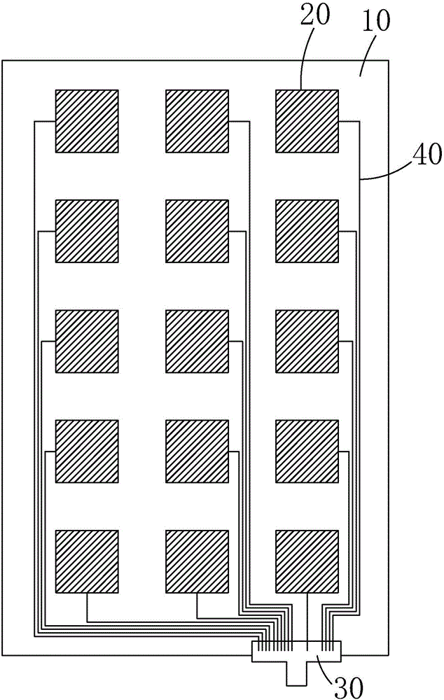
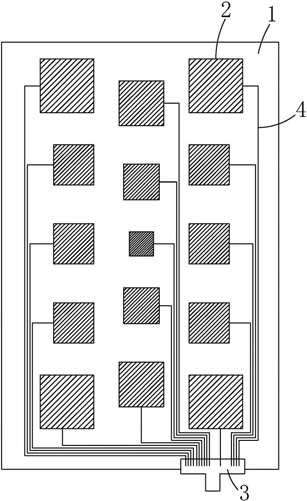
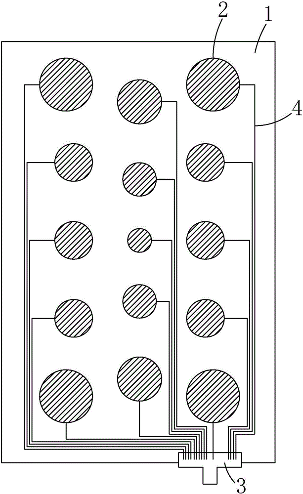
[0031] see Figure 2 to Figure 4 , the present invention provides a pressure sensor, comprising: a substrate 1, a plurality of sensing units 2 disposed on the substrate 1, disposed on the substrate 1 and respectively connected to the plurality of sensing units 2 There are several wires 4 in one-to-one correspondence, and the circuit board 3 arranged on one side of the substrate 1 .

[0032] The sensing unit 2 is connected to the circuit board 3 through the corresponding wire 4 , and transmits the sensed pressure signal to the circuit board 3 .

[0033] The plurality of sensing units 2 are arranged in a divergent form from the center of the substrate 1 to the periphery of the substrate 1;

[0034] Among the several sensing units 2, the sensin...


PUM


Abstract

The invention provides a pressure sensor and a pressure touch panel. The pressure sensor comprises a substrate (1), a plurality of sensing units (2), a plurality of wires (4) and a circuit board (3), wherein the plurality of sensing units (2) are arranged on the substrate (1), the plurality of wires (4) are arranged on the substrate (1) and are in one-to-one correspondence to the plurality of sensing units (2), the circuit board (3) is arranged at one side of the substrate (1), the plurality of sensing units (2) are radially arranged on the substrate (1) from the center of the substrate (1) to the periphery of the substrate (1), and the areas of the sensing unit (2) are gradually increased from the center of the substrate (1) to the periphery of the substrate (1). Compared with the prior art, the pressure sensor has the advantages that different regions on the surface of the pressure sensor can be enabled to have uniform sensing sensitivity, and a pressure touch experience effect of a user is improved. With the pressure touch panel provided by the invention, different regions on the surface of the pressure touch panel can be enabled to have uniform response sensitivity, and the pressure touch experience effect of the user is improved.

Description

technical field [0001] The invention relates to the technical field of touch display, in particular to a pressure sensor and a pressure touch panel. Background technique [0002] With the rapid development of smart phones, tablet computers and other electronic products, the display screen size of smart phones and tablet computers is also getting larger and larger, and the operation mode is also changing from the traditional button operation mode to the touch operation mode, followed by The rapid development of pressure touch panels. [0003] The Force Touch panel is mainly based on the deformation generated by the user's finger pressing the surface of the touch panel of the smart electronic product, and uses the Force Sensor to sense the magnitude of the pressure change, thereby realizing the force touch sensing; according to the pressure Different sensing principles, pressure touch panels can be mainly divided into three categories: piezoelectric, piezoresistive, and capac...

Claims


Application Information

Patent Timeline
Patent Type & Authority Applications(China)
IPC IPC(8): G06F3/041G06F3/044
CPCG06F3/0414G06F3/044G06F3/04164G06F3/0443G06F3/0447G06F3/0448G06F3/041G06F2203/04101
Inventor 黄耀立张红森贺兴龙
Owner WUHAN CHINA STAR OPTOELECTRONICS TECH CO LTD
Why Eureka
Try Eureka