
Multi-component part transducer assembly and a method for determining the pressure of a fluid using the transducer

a transducer and multi-component technology, applied in the direction of angiography, separation process, instruments, etc., can solve the problems of inability to accurately measure the pressure transmitted to the sensor, inability to detect linearity, and inability to accurately measure the pressure, so as to reduce the resistance to pressure, increase sensitivity, and flexible membrane

Active Publication Date: 2010-10-07
CYTIVA SWEDEN AB
View PDF14 Cites 5 Cited by
  • Summary
  • Abstract
  • Description
  • Claims
  • Application Information

AI Technical Summary

Benefits of technology

[0015]The use of a load cell, which has a rigid face rather than an elastomeric diaphragm for pressure contact with the flexible membrane, provides a more accurate measurement than prior art transducers because the rigid face has uniform sensitivity across its surface which improves the linearity of the signal received.
[0017]More preferably the one face of the adapter is modified to maximise contact between the face and the flexible membrane. Most preferably, the one face of the adapter is either planar or convex. A slightly convex face assists the removal of air bubbles, if present, which may be adjacent to the interior face of the flexible membrane and which may affect the measurement of pressure.
[0025]Preferably, the disposable component is composed of a material which is combustible. A range of suitable polymeric plastic materials are known which can be combusted. The advantage of using a combustible material is that it can be easily disposed of by incineration, thereby avoiding lengthy decontamination or cleansing procedures and has a low environmental load.
[0026]Preferably, the disposable component additionally comprises a sensor. Suitable sensors include, but are not limited to, temperature sensors, conductivity sensors and pH sensors. The advantages of combining the disposable component with an additional sensor is that it both optimises space usage on chromatography / purification system and it reduces the hold-up / dead volume of the system.
[0035]Contact between the load cell (or the adapter) and the flexible membrane is further enhanced by the inflexible or rigid nature of the load cell / adapter face which is in pressure contact with the flexible membrane as opposed to transducers known in the prior art which utilise pressure contact between two flexible membranes. The use of an inflexible or rigid face increases sensitivity by reducing the risk that any regions of the face are less responsive to pressure due to variations in flexibility.
[0036]Preferably, the step of securing the reusable component to the disposable component involves linearly aligning the components to maximise pressure contact between the load cell and the flexible membrane. Axial alignment also avoids any rotation of the parts which can lead to wear of the flexible membrane. More preferably, the assembly further comprises guide elements and the method involves linearly aligning the components by means of the guide elements.

Problems solved by technology

These procedures are both costly and time consuming.
If, for example, the membranes are not aligned axially then the pressure transmitted to the sensor may not be measured correctly.
Furthermore, the linearity of signal detected may be compromised if the flexibility of one or both membranes varies across their surface and is thus more responsive to pressure in one region of the membrane (e.g. the centre).
Another problem with the pressure transducers used in the prior art is that they have a limited operating range associated with the pressure of the body fluids that they are measuring.
While they are suitable for use at relatively low pressures (e.g. 4 Pa; 0.5 bar) they cannot be used for measuring higher pressures (e.g. in excess of 4×10⁵ Pa, 4 bar associated with bioseparations and filtrations).
The component parts of the prior art transducers are generally attached to each other by snap-on connectors which can only withstand relatively low forces acting on them to pull them apart.
Moreover, the capillary tubing used with these transducers tends to rupture at high pressures and flow rates.

Method used


Image

  • Multi-component part transducer assembly and a method for determining the pressure of a fluid using the transducer
  • Multi-component part transducer assembly and a method for determining the pressure of a fluid using the transducer
  • Multi-component part transducer assembly and a method for determining the pressure of a fluid using the transducer

Examples


Embodiment Construction

[0048]Embodiments of a multi-component part transducer assembly for measuring pressure in a fluid of interest are shown in the accompanying Figures.

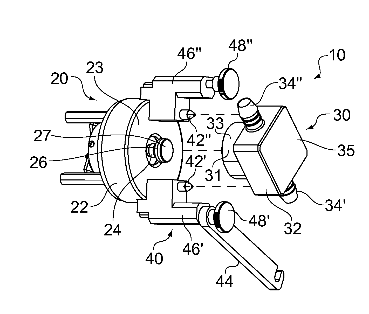
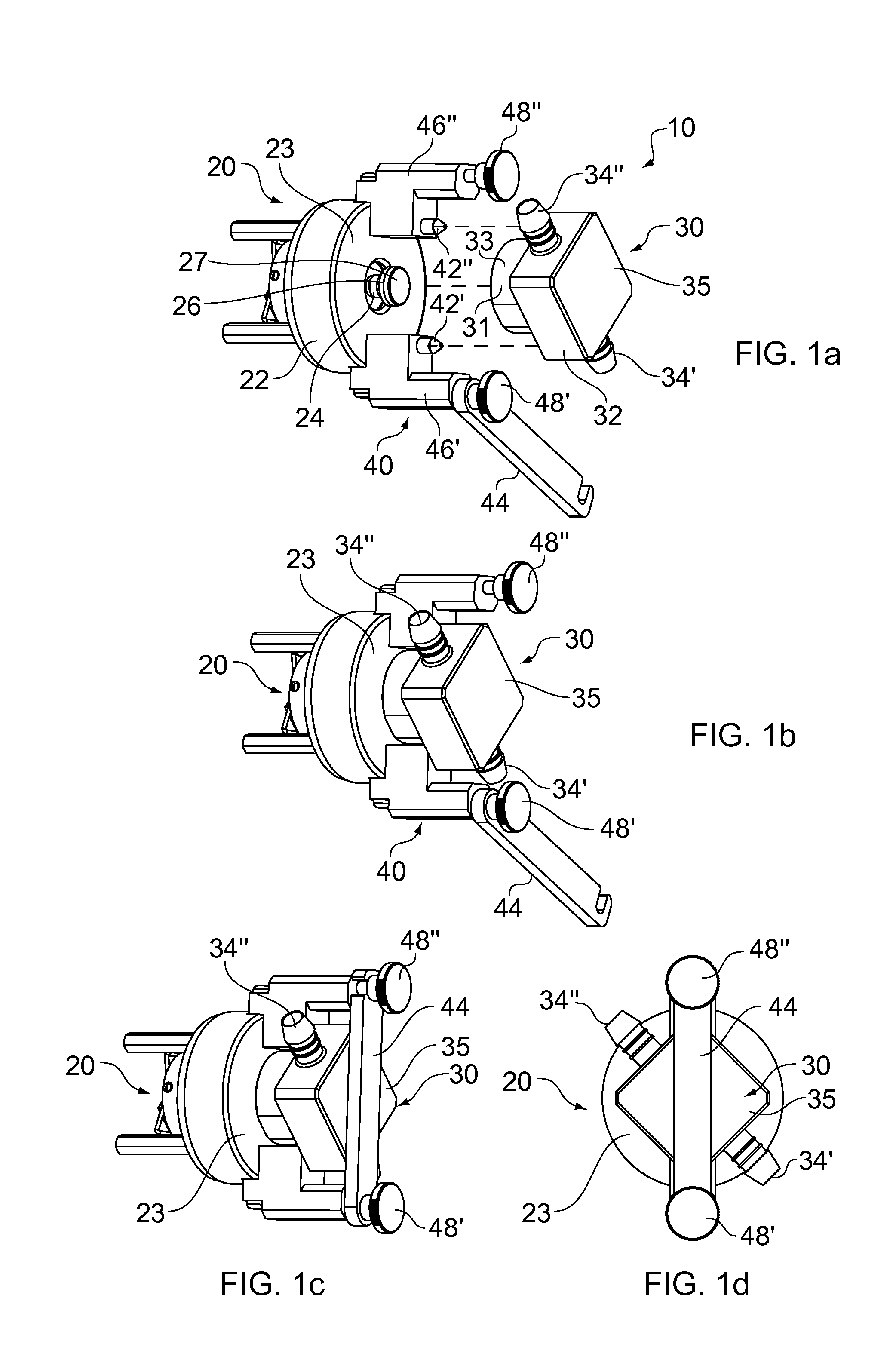
[0049]FIG. 1a gives an exploded, perspective view of a multi-component part transducer assembly 10 comprising a reusable component 20, a disposable component 30 and a locking component 40.

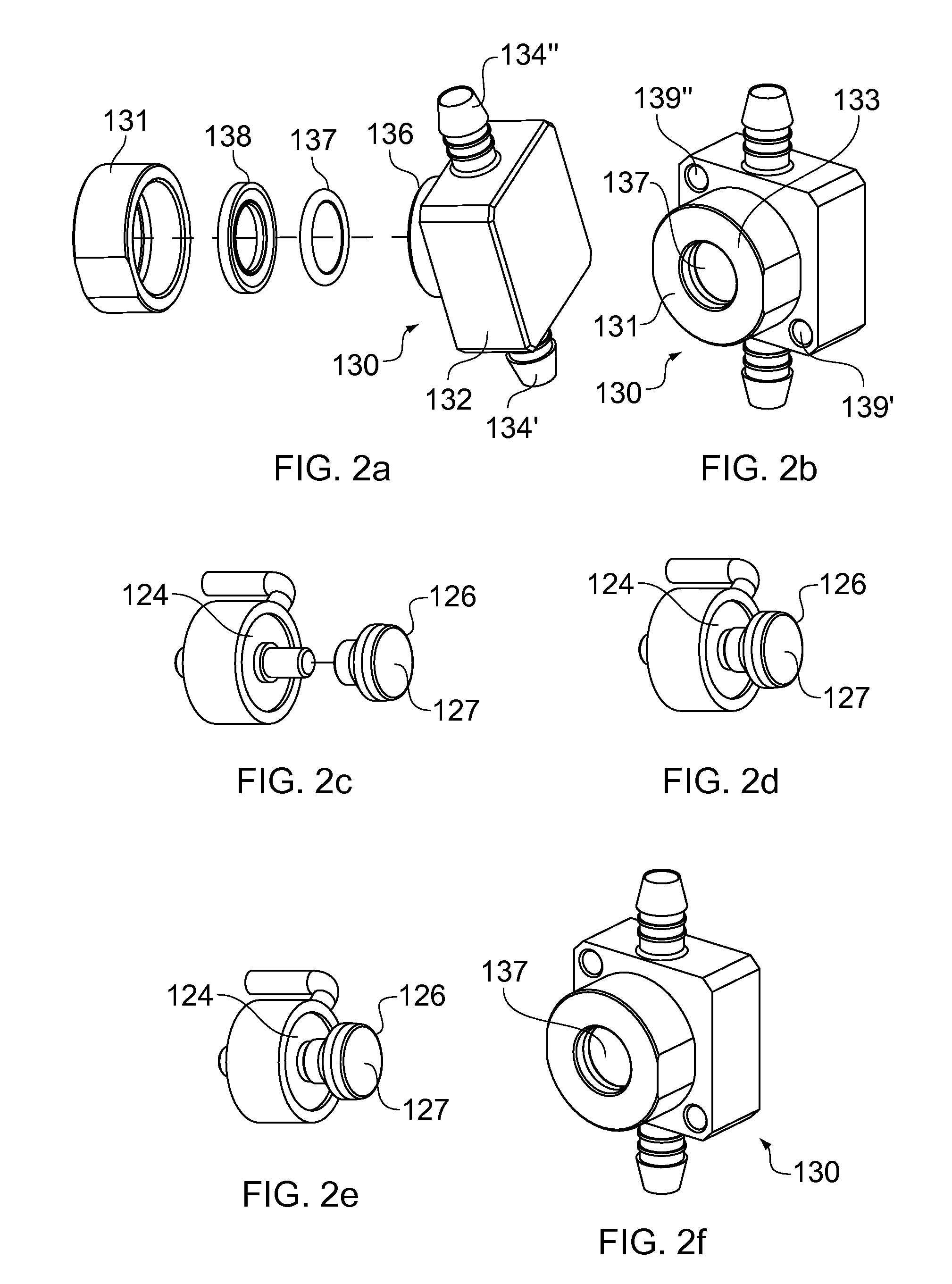
[0050]The reusable component 20 comprises a housing or body 22 for a transducer 24 in the form of a load cell; the load cell may be any standard or conventional load cell (e.g. Futek model no. LCM300-50lb (223N), Sensotest Electronics AB, Sweden). In the embodiment shown in FIG. 1a the load cell 24 has an adapter or plunger 26 which is reversibly attachable to it and which can be interchanged with other adapters or plungers 26 of varying dimensions. One face 27 of the adapter 26 may be modified to maximise contact with the face of a flexible membrane or diaphragm (FIG. 2b) in the disposable component 30 which is required in use for determining pressure,...


PUM

PropertyMeasurementUnit
forceaaaaaaaaaa
internal diameteraaaaaaaaaa
pressureaaaaaaaaaa

Abstract

The invention relates to a multi-component part transducer assembly for determining the pressure of a fluid of interest. One part of the assembly comprises a reusable transducer, another part a disposable component comprising a flexible membrane which is in pressure connection with the fluid of interest, and another part comprises a locking component for securing the reusable and disposable parts together.

Description

CROSS-REFERENCE TO RELATED APPLICATIONS[0001]This application is a filing under 35 U.S.C. §371 and claims priority to international patent application number PCT / SE2008 / 000663 filed Nov. 26, 2008, published on Jun. 4, 2009, as WO 2009 / 070085, which claims priority to patent application number 0723205.1 filed in Sweden on Nov. 27, 2007.FIELD OF THE INVENTION[0002]The present invention relates to a multi-component part transducer assembly for determining the pressure of a fluid of interest. The multi-component part transducer assembly of the invention is of particular use in the development and manufacture or pharmaceutical and biotechnological products, where it is suitable for use in a wide range of applications including chromatographic separations, filtration, dialysis and chemical synthesis.BACKGROUND OF THE INVENTION[0003]Good manufacturing practices (GMP) and governmental regulations are key to any pharmaceutical or biotechnological development or manufacturing process or proce...

Claims


Application Information

Patent Timeline
Patent Type & Authority Applications(United States)
IPC IPC(8): B01D35/14G01L9/00
CPCA61B5/0215G01L19/003G01L19/0023A61B2562/0247
Inventor JURIO, JAVIERLUNDQVIST, ROGER
Owner CYTIVA SWEDEN AB
Learn More