
Fusing method of 3D laser point cloud and 2D image

A two-dimensional image, three-dimensional laser technology, applied in image enhancement, image analysis, image data processing and other directions, can solve the problems of low calculation efficiency, large amount of data, and complicated calculation process.

Active Publication Date: 2016-11-09
DALIAN UNIV OF TECH
View PDF3 Cites 43 Cited by
  • Summary
  • Abstract
  • Description
  • Claims
  • Application Information

AI Technical Summary

Problems solved by technology

This method has the following disadvantages: 1) This method requires a comprehensive laser scanning of the calibration plate to obtain a complete 3D laser point cloud of the calibration plate, and the amount of data acquired by sampling is large
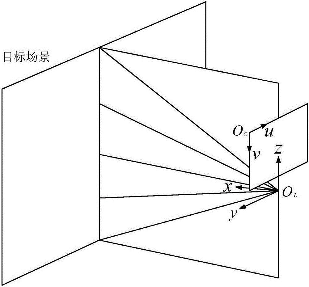
2) In order to solve the mapping relationship between the 3D laser point cloud and the 2D image, this method needs to process a large amount of sampled data, the calculation amount is too large, the calculation efficiency is low, and the calculation process is cumbersome; 3) This method cannot realize the 3D laser point cloud Real-time matching of cloud and 2D image. When 3D laser point cloud and 2D image are fused, the laser scanner needs to scan the entire scene first to obtain the 3D laser point cloud of the complete scene, and then combine it with the 3D laser point cloud obtained by the camera. Two-dimensional planar image data is fused, and the process is not real-time

Method used


Image

  • Fusing method of 3D laser point cloud and 2D image
  • Fusing method of 3D laser point cloud and 2D image
  • Fusing method of 3D laser point cloud and 2D image

Examples


Embodiment Construction

[0060] The present invention will be further described below in conjunction with accompanying drawing.

[0061] like figure 1 As shown, a fusion method of a 3D laser point cloud and a 2D image comprises the following steps:

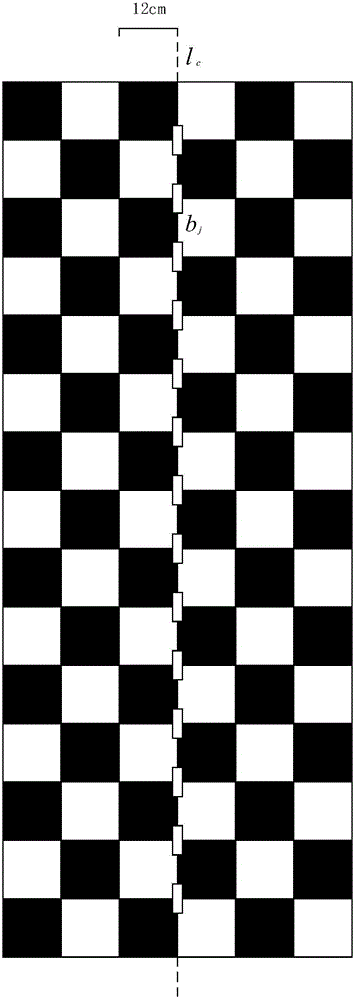
[0062] Step 1. Make a black and white grid vertical hole calibration plate. The size of the calibration plate is 180cm×72cm, and black and white square grids with a side length of 12cm are evenly distributed on it, along the center line of the calibration plate l c 14 vertical holes are evenly arranged B={b j |1≤j≤14}, the length of the vertical hole is 6cm, the width is 2cm, and the center of each vertical hole is c j (1≤j≤14) are located at the corners of the black and white grid, such as figure 2 shown.

[0063] Step 2. Collect 3D laser point clouds and 2D images, fix the laser scanner and camera, and face the calibration plate vertically to the laser scanner and camera. When scanning with the laser scanner, the reflection of laser light will form...


PUM


Abstract

The invention relates to the technical field of 3D point cloud data processing and 3D scene reconstruction. A fusing method of a 3D laser point cloud and a 2D image comprises the following steps: (1) making a black-and-white grid vertical hole calibration board; (2) collecting 3D laser point cloud and 2D images; (3) calculating the space coordinates of the centers of the vertical holes; (4) calculating the pixel coordinates of the centers of the vertical holes; and (5) calculating a mapping matrix to complete data fusion. The method has the advantages as follows: firstly, linear point cloud data of a laser scanner and image data shot by a camera are used, and the amount of data sampled is small; secondly, for solving of the mapping relation between 3D laser point cloud and 2D images, the amount of calculation is small, the calculation process is simple, and the calculation efficiency is high; thirdly, real-time 3D laser point cloud and 2D image fusion can be realized; fourthly, the space coordinates of the centers of the vertical holes are calculated using an interval matrix, there are multiple constraints, and calculation is more accurate; and fifthly, the homographic relation between the laser scanning plane and the camera imaging plane is directly constructed based on the imaging principle of the camera to solve the mapping matrix, and the calculation method is simple and reliable.

Description

technical field [0001] The invention relates to a fusion method of a three-dimensional laser point cloud and a two-dimensional image, belonging to the technical fields of three-dimensional point cloud data processing and three-dimensional scene reconstruction. Background technique [0002] In the process of digitizing the real world, the 3D point cloud data records the geometric properties and position information of the object surface, and the 2D image records the color information and texture information of the object surface. The deep fusion of the two will form an emerging digital Media, that is, 3D color point cloud data, 3D color point cloud data is a further development of 3D point cloud data, which can more accurately represent the real world. The fusion of 3D laser point cloud and 2D image is a key technology to solve 3D scene reconstruction. It has strong theoretical significance and application value. It has been used in industrial inspection, autonomous navigatio...

Claims


Application Information

Patent Timeline
IPC IPC(8): G06T7/00G06T5/50
CPCG06T5/50G06T2207/10024G06T2207/10028G06T2207/30208
Inventor 安毅熊宇聪刘倩倩韩玮荣
Owner DALIAN UNIV OF TECH
Learn More