Method and system for testing infrared remote control

A technology of infrared remote control and test method, applied in signal transmission systems, non-electrical signal transmission systems, instruments, etc., can solve the problems of multi-manual operation, low work efficiency, high labor cost, and achieve lower frequency, lower cost, and lower labor costs. desired effect

Inactive Publication Date: 2016-11-09
SHENZHEN C&D ELECTRONICS
View PDF5 Cites 5 Cited by
  • Summary
  • Abstract
  • Description
  • Claims
  • Application Information

AI Technical Summary

Problems solved by technology

[0002] When the existing infrared remote control needs to test whether the current and hardware work normally, it is necessary to power on the PCBA of the remote control, and then press the button on the infrared remote control with a conductive fixture to test whether the hardware of the infrared remote control is normal. Normal and whether the working current is normal, such a test method requires more manual operations, high labor costs, and low work efficiency

Method used


Image

  • Method and system for testing infrared remote control
  • Method and system for testing infrared remote control
  • Method and system for testing infrared remote control

Examples


Embodiment 1

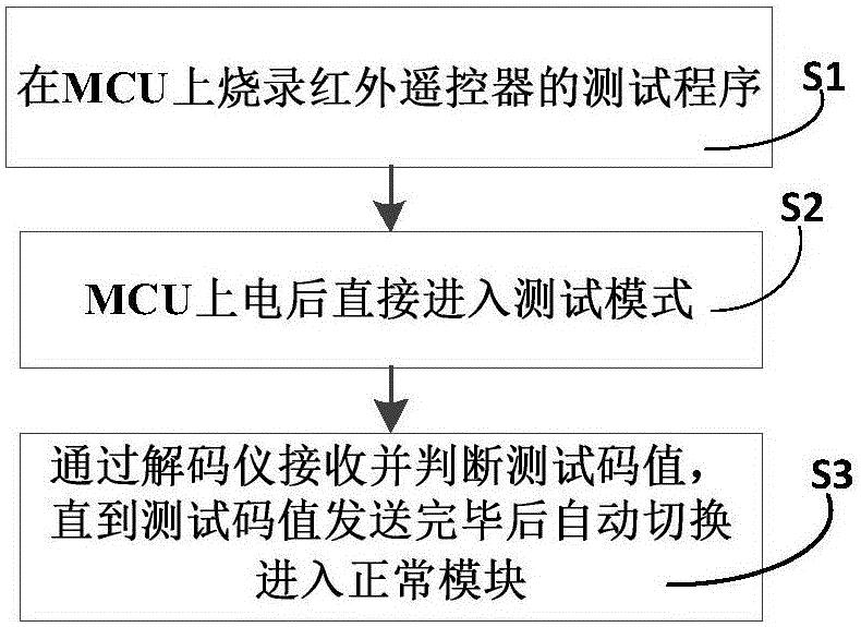
[0022] like figure 1 and figure 2 As shown, this example provides a test method for an infrared remote control, including the following steps:

[0023] Step S1, burning the test program of the infrared remote controller on the MCU;

[0024] Step S2, wait until the MCU is powered on, then directly enter the test mode according to the test program, and the MCU outputs the test code value;

[0025] Step S3, receiving and judging the test code value through the decoder, and entering the normal module through the MCU until the test code value is sent.

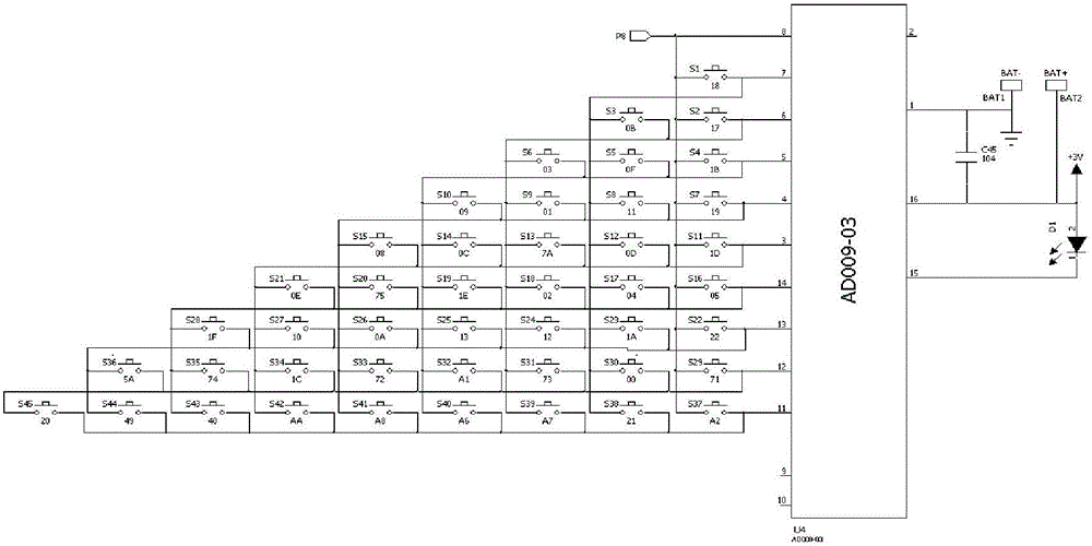
[0026] The step S1 described in this example is used to enable the MCU to automatically send the test code value through the preset test program, and the test code value is image 3 Each button code value shown in the circuit diagram can then be used to detect whether the hardware of the infrared remote controller is normal; in the step S2, after entering the test mode, the IO port of the MCU outputs an infrared test through an ...

Embodiment 2

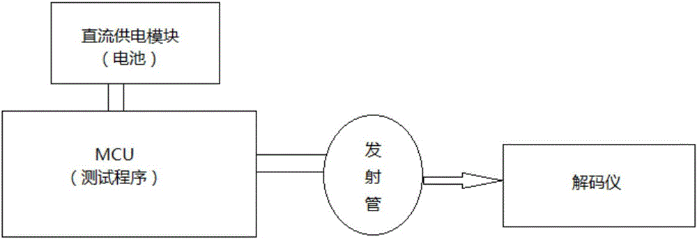
[0033] This example also provides a testing system for an infrared remote controller, which adopts the testing method for an infrared remote controller as described in Embodiment 1, and includes a DC power supply module connected to the MCU.

[0034] This example also preferably includes a current test fixture, the DC power supply module is arranged on the current test fixture, when the infrared remote controller is placed on the current test fixture, the DC power supply module is connected to realize the MCU. Electricity, and automatically realize the detection of the current value. Therefore, in this example, it is only necessary to place the infrared remote controller on the current test fixture to automatically detect whether the hardware and working current of the infrared remote controller are normal.


PUM


Abstract

The invention provides a method and a system for testing an infrared remote control. The testing method comprises the following steps: S1, burning a test program of the infrared remote control on an MCU; S2, entering a test mode according to the test program after waiting until the MCU is directly electrified, wherein the MCU outputs a test code value; and S3, receiving and judging the test code value through a decoder, and entering a normal module through the MCU after the test code value is completely transmitted. According to the invention, after the infrared remote control is electrified, the MCU automatically enters the pre-burnt test program, then the test code value is immediately and automatically transmitted, and the MCU controls the infrared remote control to enter the normal mode after the test is completed; and therefore, a tester only needs to electrify and observe the test data in the test mode, and an operating mode of the infrared remote control does not need to be switched after test is completed. Therefore, the production testing efficiency can be greatly improved, and the cost is reduced.

Description

technical field [0001] The invention relates to a testing method, in particular to a testing method of an infrared remote controller, and to a system using the testing method of the infrared remote controller. Background technique [0002] When the existing infrared remote control needs to test whether the current and hardware work normally, it is necessary to power on the PCBA of the remote control, and then press the button on the infrared remote control with a conductive fixture to test whether the hardware of the infrared remote control is normal. Whether it is normal and whether the working current is normal, such a test method requires more manual operations, high labor costs, and low work efficiency. Contents of the invention [0003] The technical problem to be solved by the present invention is to provide a test method for an infrared remote controller that can reduce labor costs and improve work efficiency, and relates to a system using the test method for an inf...

Claims


Application Information

Patent Timeline
Patent Type & Authority Applications(China)
IPC IPC(8): G08C25/00G08C23/04
CPCG08C25/00G08C23/04
Inventor 李文斌
Owner SHENZHEN C&D ELECTRONICS
Why Eureka
Try Eureka