Automatic gear generating device

A gear fan forming and automatic technology, applied in the field of machinery, can solve problems such as difficulty in obtaining tooth shape, low efficiency, cumbersome operation, etc., and achieve the effect of improving accuracy, saving labor and time

Inactive Publication Date: 2016-11-09
UNIV OF SHANGHAI FOR SCI & TECH
View PDF7 Cites 3 Cited by
  • Summary
  • Abstract
  • Description
  • Claims
  • Application Information

AI Technical Summary

Problems solved by technology

This method is time-consuming, cumbersome to operate, very inefficient, and the removed part is not intuitive, and the displacement of the manually moved rack is different every time, and it is difficult to obtain the ideal tooth shape.

Method used


Image

  • Automatic gear generating device
  • Automatic gear generating device
  • Automatic gear generating device

Examples


Embodiment

[0025] The specific implementation manners of the embodiments of the present invention will be described below in conjunction with the accompanying drawings.

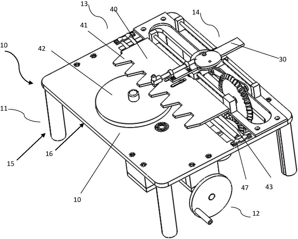
[0026] figure 1 It is the overall structure diagram of the automatic gear forming device in the embodiment of the present invention.

[0027] like figure 1 As shown, the automatic gear forming device 10 includes a fixing part 11 , a driving part 12 , a forming part 13 and a drawing part 14 .

[0028] The fixing part 11 has a fixing unit 15 and a supporting unit 16 .

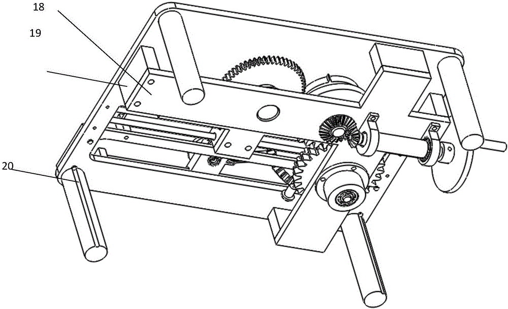
[0029] figure 2 It is a bottom oblique view of the automatic gear forming device in the embodiment of the present invention.

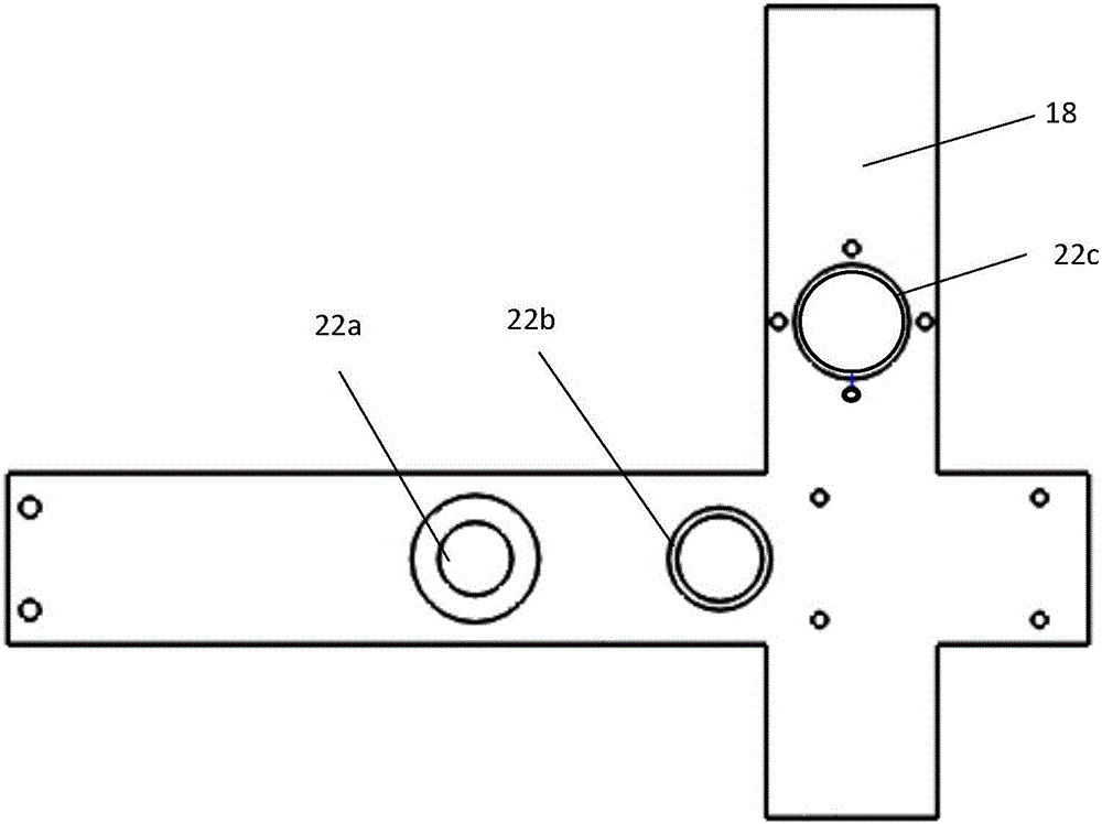
[0030] like figure 2 As shown, the fixing unit 15 has a fixing plate 17 , a cross plate 18 and four connecting blocks 19 . The upper sides of the four ends of the cross plate 18 are respectively connected with the lower ends of the four vertical connecting blocks 19 by screws, and the upper ends of the four connecting block...


PUM


Abstract

The invention relates to an automatic gear generating device. According to the automatic gear generating device, multiple sets of straight gear, bevel gears and intermittent gears are adopted to carry out transmission, power can be transmitted to a generating component and a line drawing portion by only shaking a handle, and the first intermittent gear and the second intermittent gear can push a line drawing pen, a sticker disk and a toothed plate to move periodically, so that the pen automatically records envelope lines cut in the gear processing process through mutual cooperation of the movements, manual line drawing is not required, and a lot of labor and time is saved. In addition, input of the displacement of the toothed plate is carried out automatically through gear transmission, the moving distance is fixed at each time, manual push is not required, and the experiment accuracy is improved.

Description

technical field [0001] The invention relates to an automatic gear forming device, which belongs to the field of machinery. Background technique [0002] Fancheng method is the most commonly used method in gear machining at present. It is processed according to the principle that when a pair of gears mesh and drives, the tooth profiles of the two gears are conjugate curves, so it is also called conjugate method or envelope method. [0003] At present, in school teaching demonstrations, students are required to first calculate the size of the addendum circle and the index circle, and then push the rack to move a few millimeters of displacement, use a pencil to draw a line along the tooth profile of the rack, and repeat The two actions of pushing and drawing lines are performed to form the envelope of the tooth shape to be cut. This method is time-consuming, cumbersome to operate, very inefficient, and the resected part is not intuitive, and the displacement of the manually mo...

Claims


Application Information

Patent Timeline
IPC IPC(8): G09B25/02
CPCG09B25/02
Inventor 麦云飞刘志亮海军李丹提孙晓萌孙辉刘杰陈永芝
Owner UNIV OF SHANGHAI FOR SCI & TECH
Why Eureka
Try Eureka