A multi-channel connector

A connector and multi-channel technology, applied in the direction of connection, two-part connection device, and components of the connection device, etc., can solve the problems of complex socket and plug manufacturing process, difficult to improve product quality, and no support for quick-plug installation, etc. Simple and convenient maintenance and repair, reduce the generation of electrical contact interference sources, and maintain the effect of impedance continuity

Active Publication Date: 2019-01-29
WUTONG HLDG GRP CO LTD
View PDF4 Cites 1 Cited by
  • Summary
  • Abstract
  • Description
  • Claims
  • Application Information

AI Technical Summary

Problems solved by technology

[0004] 1. The socket and plug are generally connected by threads (or flange screws), which do not support quick-plug installation;
[0005] 2. The contact pairs of its components cannot be disassembled after assembly, let alone interchangeable and universal;
[0006] 3. The manufacturing process of the socket and plug is complicated, especially after assembly, glue injection and packaging are required, which increases the manufacturing cost, but it is difficult to improve the product quality

Method used


Image

  • A multi-channel connector
  • A multi-channel connector
  • A multi-channel connector

Examples


Embodiment 1

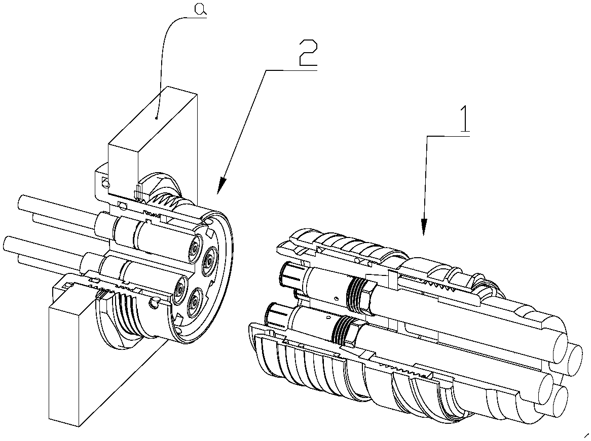
[0041] refer to Figure 1-3 , a circular multi-channel connector, including a plug 1 and a socket 2, the plug 1 is matched with the socket 2 and inserted into the communication device a.

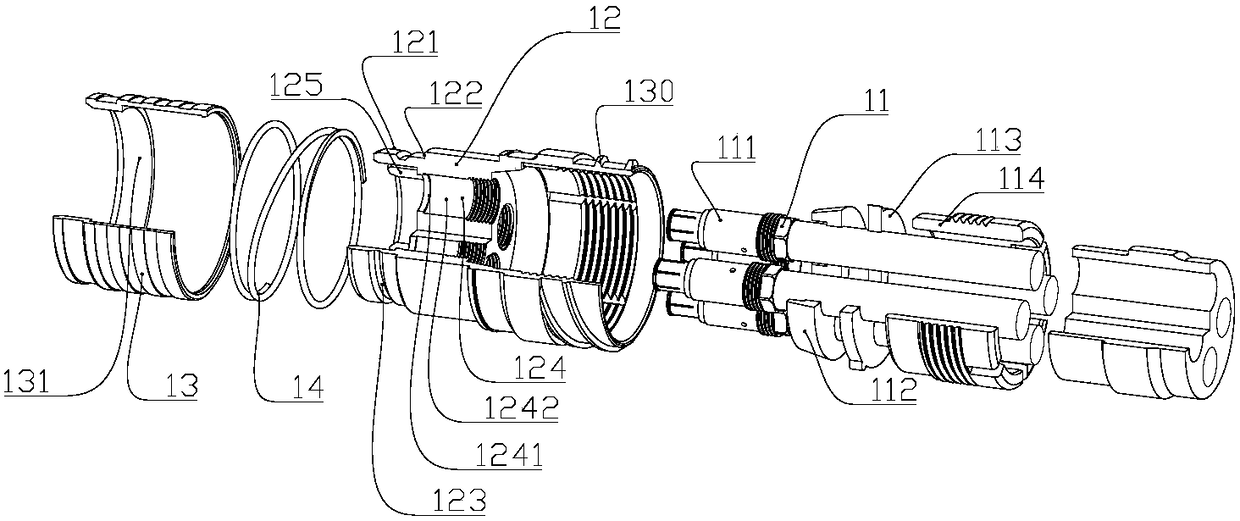
[0042] like figure 2 As shown, the plug 1 includes a needle assembly 11, a first housing 12, an unlocking sleeve 13 and an elastic member 14; the needle assembly 11 is inserted in the first housing 12, the first housing 12 is inserted in the unlocking sleeve 13, and the elastic member 14 It is installed between the first shell 12 and the unlocking sleeve 13 . The first shell 12, the unlocking sleeve 13, and the elastic member 14 are all circular structures.

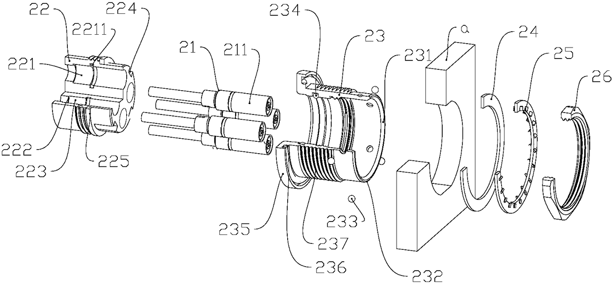
[0043] like Figure 7 As shown, there are at least two groups of needle assemblies 11, and each group of needle assemblies 11 includes a needle contact 111, and also includes a porous sealing gasket 112, a porous pressing plate 113 and a fastening screw sleeve 114; a porous sealing gasket 112, a porous pressing plate 113 and a tight...

Embodiment 2

[0054] like Figure 4-6 As shown, a square multi-channel connector includes a plug 1 and a socket 2. The plug 1 is mated with the socket 2 and inserted into the communication device a.

[0055] The plug 1 includes a needle assembly 11, a first housing 12, an unlocking sleeve 13 and an elastic member 14; the needle assembly 11 is inserted side by side in the first housing 12, the first housing 12 is inserted in the unlocking sleeve 13, and the elastic member 14 is mounted on Between the first shell 12 and the unlocking sleeve 13 . The structures of the needle assembly 11 and the hole assembly 21 are the same as those of the first embodiment. The first shell 12, the unlocking sleeve 13, and the elastic member 14 are all rectangular structures. In addition, compared with the embodiment 1, the plug 1 of this embodiment has no primary key and secondary key, and the socket 1 has no primary keyway corresponding to the primary key and secondary key. , The structure of the secondary ...


PUM


Abstract

The invention discloses a multichannel connector. The connector comprises a plug and a socket. The plug and the socket are connected in a matching mode. The plug comprises a needle assembly, a first shell, an unlocking sleeve and an elastic component. One end of an outer wall of the first shell is provided with a first marking surface along an outer-wall circumferential direction. The socket comprises a hole assembly, a lining and a second shell. A second marking surface is arranged on an outer wall of one end on the second shell along a circumferential direction, wherein the end matches with the plug. By using the plug and the socket of the connector, through aligning the first marking surface of the plug and the second marking surface of the socket, the plug can be rapidly inserted into the socket, and during dismounting, only one hand needs to held the unlocking sleeve of the plug and the plug can be directly removed. Assembling is stable and dismounting is convenient.

Description

technical field [0001] The invention belongs to the technical field of mobile communication connectors, and in particular relates to a multi-channel connector. Background technique [0002] In mobile communication RF systems, RF multi-channel, low-frequency multi-channel and mixed-frequency multi-channel connectors have unique application advantages in radio frequency transmission equipment, which can easily realize the modularization of various electrical transmission interconnection ports and product customization. Serialization can minimize the installation space of equipment, maximize the high efficiency from manufacturing to application, and maximize the internal quality and appearance quality of communication equipment. [0003] However, with the rapid development of mobile communication technology, the current multi-channel connectors on the market have also shown the following defects and deficiencies after several years of application: [0004] 1. The socket and pl...

Claims


Application Information

Patent Timeline
Patent Type & Authority Patents(China)
IPC IPC(8): H01R13/04H01R13/10H01R13/52H01R13/625H01R13/631H01R13/633H01R13/6473H01R24/20H01R24/28
CPCH01R13/04H01R13/10H01R13/5202H01R13/521H01R13/625H01R13/631H01R13/633H01R13/6473H01R24/20H01R24/28
Inventor 陈国华梁国刘建业马乃祉
Owner WUTONG HLDG GRP CO LTD
Why Eureka
Try Eureka