Bare terminal protection mechanism of power line

A technology of bare wire terminal and protection mechanism, which is applied in the field of protection mechanism of power line bare wire terminal, which can solve the problems of easy damage, clamping by shear force, and easy falling off, etc.

Active Publication Date: 2016-11-09
STATE GRID PUTIAN ELECTRIC POWER SUPPLY +2
View PDF5 Cites 4 Cited by
  • Summary
  • Abstract
  • Description
  • Claims
  • Application Information

AI Technical Summary

Problems solved by technology

In this solution, the terminal clamping hole is composed of the first through hole and the second through hole, so there are the following disadvantages: 1. The first through hole and the second through hole are staggered to achieve clamping, and the clamped power cord is bare The wire terminal is subjected to shearing force, and the power cord is easy to loose strands and easily damaged; 2. Clamping by shearing force, the clamping strength is not strong, and it is easy to fall off

Method used


Image

  • Bare terminal protection mechanism of power line
  • Bare terminal protection mechanism of power line
  • Bare terminal protection mechanism of power line

Examples


Embodiment Construction

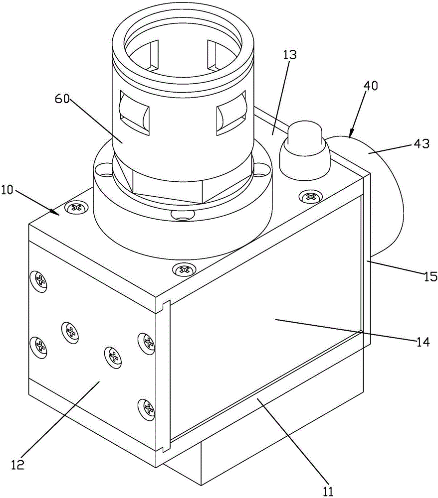
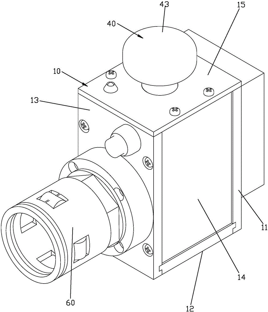
[0028] Please check Figure 1 to Figure 8 , The power cord bare wire terminal protection mechanism includes a solid base 10 , a clamping fastening block 20 , a clamping moving block 30 , an operating member 40 and an elastic body 50 .

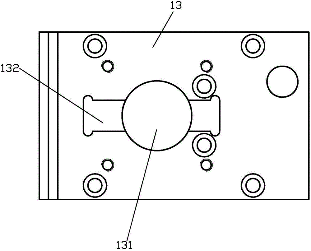
[0029] The fixing base 10 includes a bottom plate 11 , a rear plate 12 , an upper cover plate 13 and two side plates 14 . The back plate 12 is fixed on the bottom plate 11, the two side plates 14 are spaced left and right and fixed on the bottom plate 11, the rear sides of the two side plates 14 are fixed on the back plate 12, and the upper cover plate 13 is fixed on the bottom plate 11. The top surface of the rear panel 12 and the side panels 14.

[0030] The clamping block 20 is affixed to the fixed seat 10. In the specific structure: the clamping block 20 is affixed between the bottom plate 11 and the upper cover plate 13, and the clamping block 20 is interposed between the two side plates 14 , There is a gap between the clamping block 20 ...


PUM


Abstract

The invention discloses a bare terminal protection mechanism of a power line. The bare terminal protection mechanism comprises a fixed seat, a clamping fixed block, a clamping moving block, an operation element and an elastic body, wherein clamping fixed block is fixedly connected with the fixed seat, the clamping moving block is connected with the fixed seat in a sliding way so as to approach to or depart from the clamping fixed block, side surfaces opposite to each other of the clamping fixed block and the clamping moving block both are inner concave surfaces, stop grooves are formed in two sides of the two inner concave surfaces in a sunken way and penetrate through along a sliding direction, the two sides of the two inner concave surfaces are provided with bulge parts corresponding to the stop grooves, the bulge parts and the stop grooves of the two inner concave surfaces are adapted so that the bulge part of arbitrary one inner concave surface can be inserted into the stop groove of the other inner concave surface and a bare terminal of the power line is clamped by the two inner concave surface, the operation element can be used for driving the clamping moving block to slide, and the elastic body is arranged between the fixed seat and the clamping moving block in a jacking-up way so that an elastic force approaching towards the clamping fixed block is applied to the clamping moving block. The bare terminal protection mechanism has the following advantages that the diameter size change range of clamping terminals of the two concave surfaces is large, clamping forces applied to the terminals are an acting force and a counter-acting force which interact with each other, and the clamping strength is high.

Description

technical field [0001] The invention relates to a protection mechanism for bare wire terminals of power lines. Background technique [0002] During the power outage transformation of the low-voltage distribution network, it is often encountered that the original household connection line needs to be removed first, and the connection should be restored after the main line is replaced. In order to prevent people from being injured by electric shock caused by accidental calls, the State Grid Fujian Electric Power Co., Ltd.'s "Implementation Rules for Power Distribution Safety Work Regulations (Trial)" (Mindian Safety Supervision [2014] No. 389) stipulates: For those who cannot install grounding wires Self-contained power supply, low-voltage dual power supply user branch line or household line should be untied by means of low-voltage live work, and wrapped and fixed with insulation; the disassembled lead wire and disconnected wire end should be covered with insulation wrapping m...

Claims


Application Information

Patent Timeline
Patent Type & Authority Applications(China)
IPC IPC(8): H02G1/12H02G1/14
CPCH02G1/1204H02G1/14
Inventor 曾国忠吴健仁刘升关明峰肖颂勇李瑞华贺健伟洪雄伟林明星林忠喜魏嘉建
Owner STATE GRID PUTIAN ELECTRIC POWER SUPPLY
Why Eureka
Try Eureka