Magnetic eddy current safety speed coupler

A magnetic eddy current and coupler technology, which is applied in the field of couplers, can solve the problems of easy demagnetization of magnets, product scrapping, and reduced product life, and achieve the effects of eliminating unstable factors, short maintenance time, and prolonging service life

Active Publication Date: 2018-07-06
四川易尚天交实业有限公司
View PDF6 Cites 0 Cited by
  • Summary
  • Abstract
  • Description
  • Claims
  • Application Information

AI Technical Summary

Problems solved by technology

[0006] The invention mainly solves the problem in the prior art that when the load is overloaded or stuck, the magnet is easily demagnetized, the product life is reduced or even the product is scrapped, and a magnetic eddy current safety speed-regulating coupler that solves the above problems is provided.

Method used


Image

  • Magnetic eddy current safety speed coupler
  • Magnetic eddy current safety speed coupler

Examples


Embodiment 1

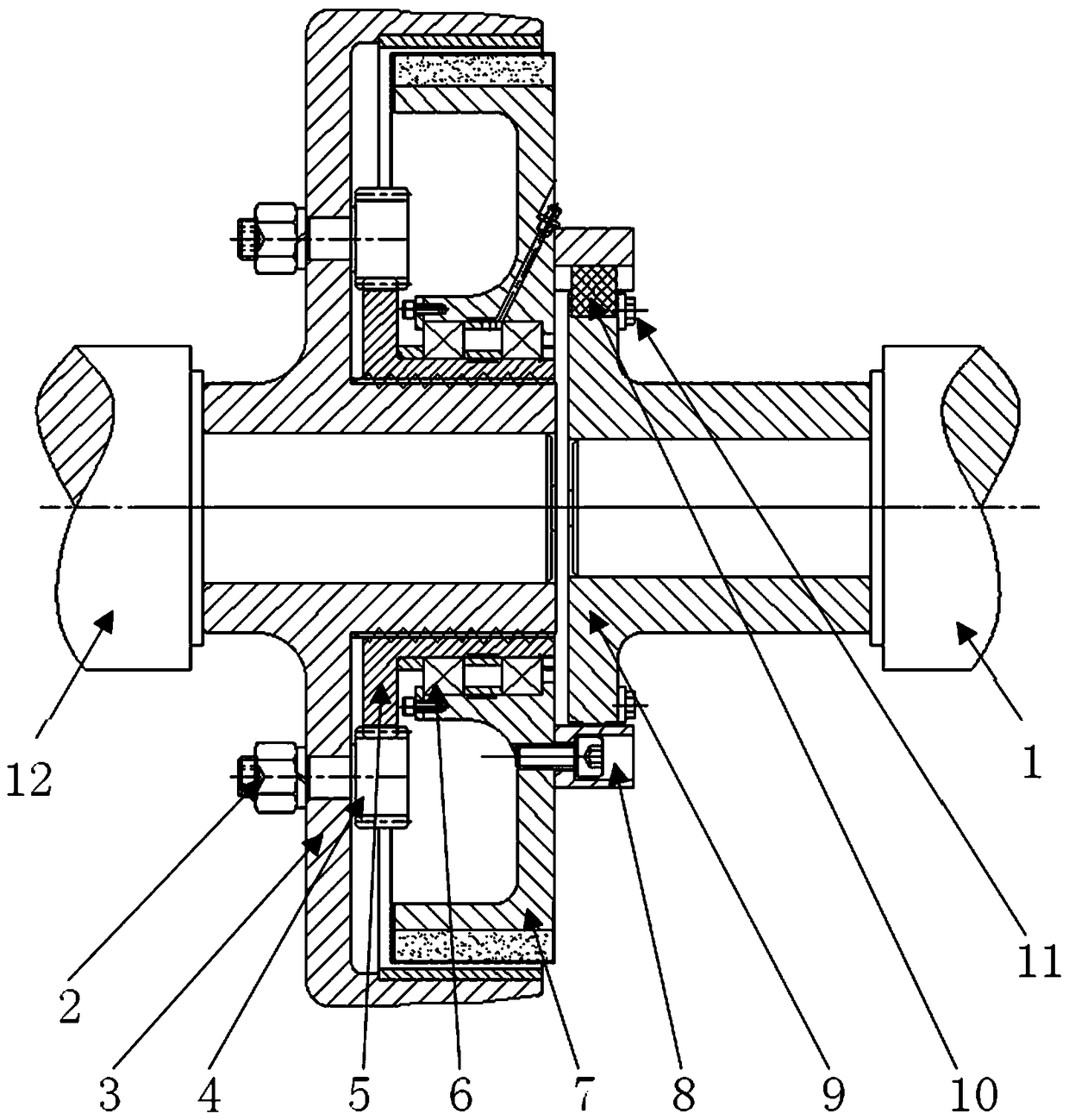
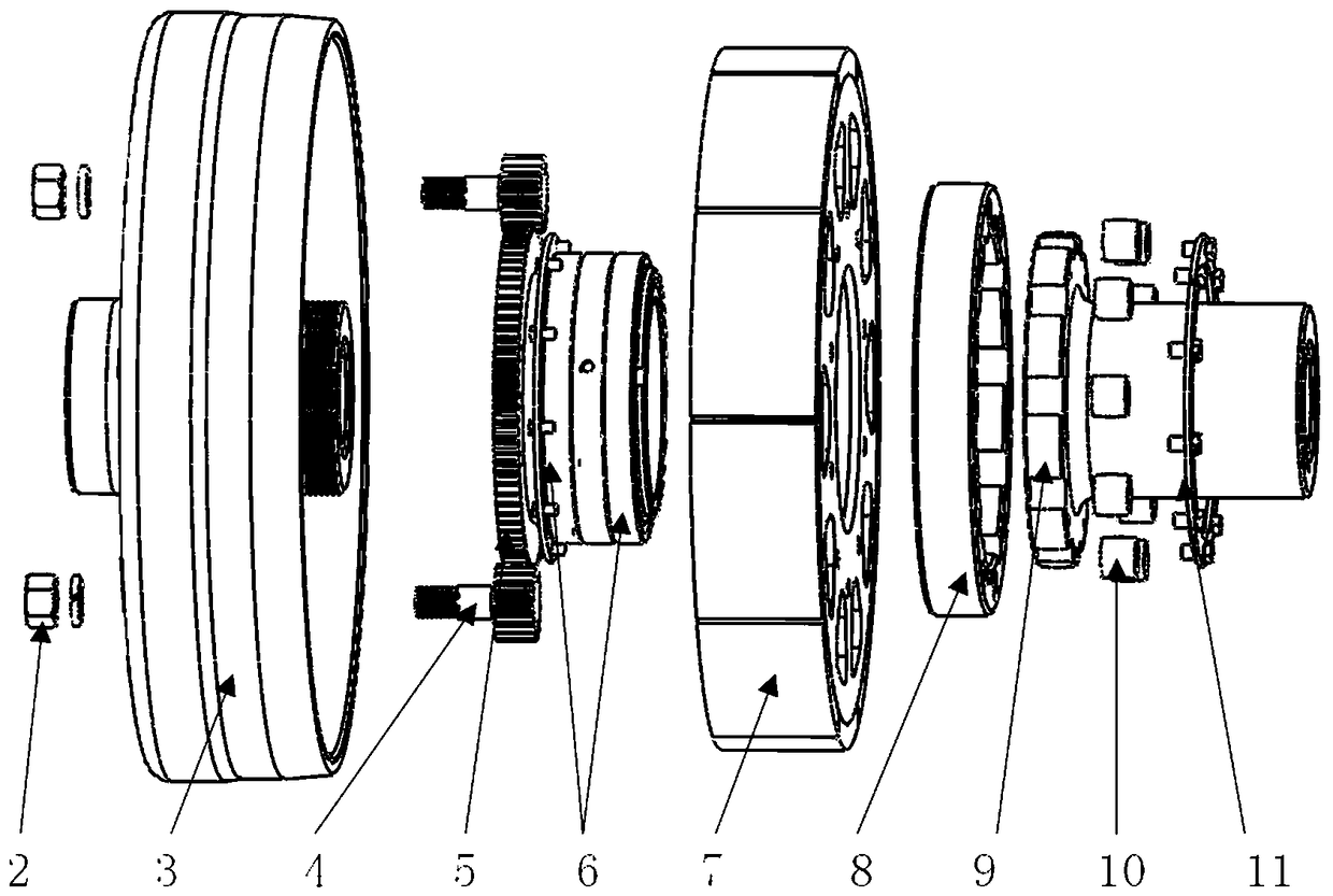
[0038] The magnetic eddy current safety speed-regulating coupler includes a motor connecting shaft 12, an outer rotor 3, an inner rotor 7, and a driven shaft 1. The motor connecting shaft 12 is integrated with the outer rotor 3, and the inner rotor 7 is integrated with the driven shaft 1. The outer rotor 3 and the inner rotor 7 are respectively provided with copper rings or magnets, that is, when the outer rotor 3 is a copper ring, the inner rotor 7 is a magnet; when the outer rotor 3 is a magnet, the inner rotor 7 is a copper ring. There is an air gap between the copper ring and the magnet.

[0039] In this embodiment, the structure between the inner rotor 7 and the driven shaft 1 is optimized, and the specific settings are as follows:

[0040] The pin ring 8 is fixed on the inner rotor 7 , and one end of the driven flange 9 is connected to the driven shaft 1 , and the other end is arranged at the position of the pin ring 8 . An arc-shaped safety pin 10 is arranged between ...

Embodiment 2

[0044] The difference between this embodiment and Embodiment 1 is that the arc-shaped safety pin 10 in this embodiment is made of nylon material.

Embodiment 3

[0046] The difference between this embodiment and Embodiment 1 or 2 is that in order to achieve the purpose of fixing the air gap between the copper ring and the magnet, the structure between the outer rotor 3 and the inner rotor 7 is optimized in this embodiment, such as figure 1 and figure 2 As shown, the specific settings are as follows:

[0047] The motor connecting shaft 12 is provided with an extension section extending to the position of the driven shaft 1. The extension section is located between the outer rotor 3 and the inner rotor 7. The inner rotor 7 is provided with a parallel section parallel to the extension section. The section and the extension section are connected by angular contact ball bearings 6 .

[0048]Through the setting of the above structure, the air gap between the copper rings on the outer rotor 3 and the inner rotor 7 and the magnets can be effectively ensured.


PUM


Abstract

The invention discloses a magnetic vortex safety speed regulation coupler solving the problem that a magnet is easily demagnetized, the product life is shortened and even the product is scrapped when a load is overloaded or stuck in the prior art. The magnetic vortex safety speed regulation coupler of the present invention comprises a motor connecting shaft (12), an outer rotor (3) arranged on the motor connecting shaft (12), an inner rotor (7) matched with the outer rotor (3) and a driven shaft (1) arranged on an inner rotor (7). The magnetic vortex safety speed regulation coupler is characterized in that the inner rotor (7) is fixedly connected with the driven shaft (1) through a driven flange; the driven flange (9) is fixedly connected with the driven shaft (1); and the driven flange (9) 9) is connected to the inner rotor (7) by an arc safety pin (10). The magnetic vortex safety speed regulation coupler of the invention has the advantages of improving the effective utilization ratio of the magnetic field of the magnet, realizing a simple speed regulating function, having an overload safety protection function, compensating for shaft system deviation, damping, tuning characteristics, etc.

Description

technical field [0001] The invention relates to a coupler, in particular to a magnetic eddy current safety speed-regulating coupler. Background technique [0002] At present, the magnetic eddy current couplers on the market are divided into planar drives and coaxial (or cylindrical) drives. [0003] Due to its structural characteristics and working principle, the plane type transmission does not require high coaxiality of the two shafts during installation. [0004] For the coaxial drive, there is a certain air gap between the main and driven rotors. The smaller the air gap, the higher the effective use of the magnetic field of the magnet, but the higher the requirements for the installation quality, the larger the air gap is. , the worse the effective use of the magnetic field of the magnet, the lower the installation requirements. Therefore, during design, the required torque of the drive can be obtained by adjusting the size of the air gap radius. However, under the co...

Claims


Application Information

Patent Timeline
Patent Type & Authority Patents(China)
IPC IPC(8): H02K49/04H02K49/10
CPCH02K49/04H02K49/10
Inventor 魏稼丰阳勇冯春安
Owner 四川易尚天交实业有限公司
Why Eureka
Try Eureka