A swirl excitation generator used for power supply of wind power gearbox monitoring system

A technology for wind power gearboxes and monitoring systems, applied to piezoelectric effect/electrostrictive or magnetostrictive motors, wind power engines, generators/motors, etc., to achieve a wide range of applications

CN106100442BInactive Publication Date: 2017-12-15ZHEJIANG NORMAL UNIVERSITY
4 Cites 0 Cited by

Patent Information

Authority / Receiving Office
CN · China
Patent Type
Patents(China)
Current Assignee / Owner
Publication Date
2017-12-15
Estimated Expiration
Not applicable · inactive patent

Smart Images

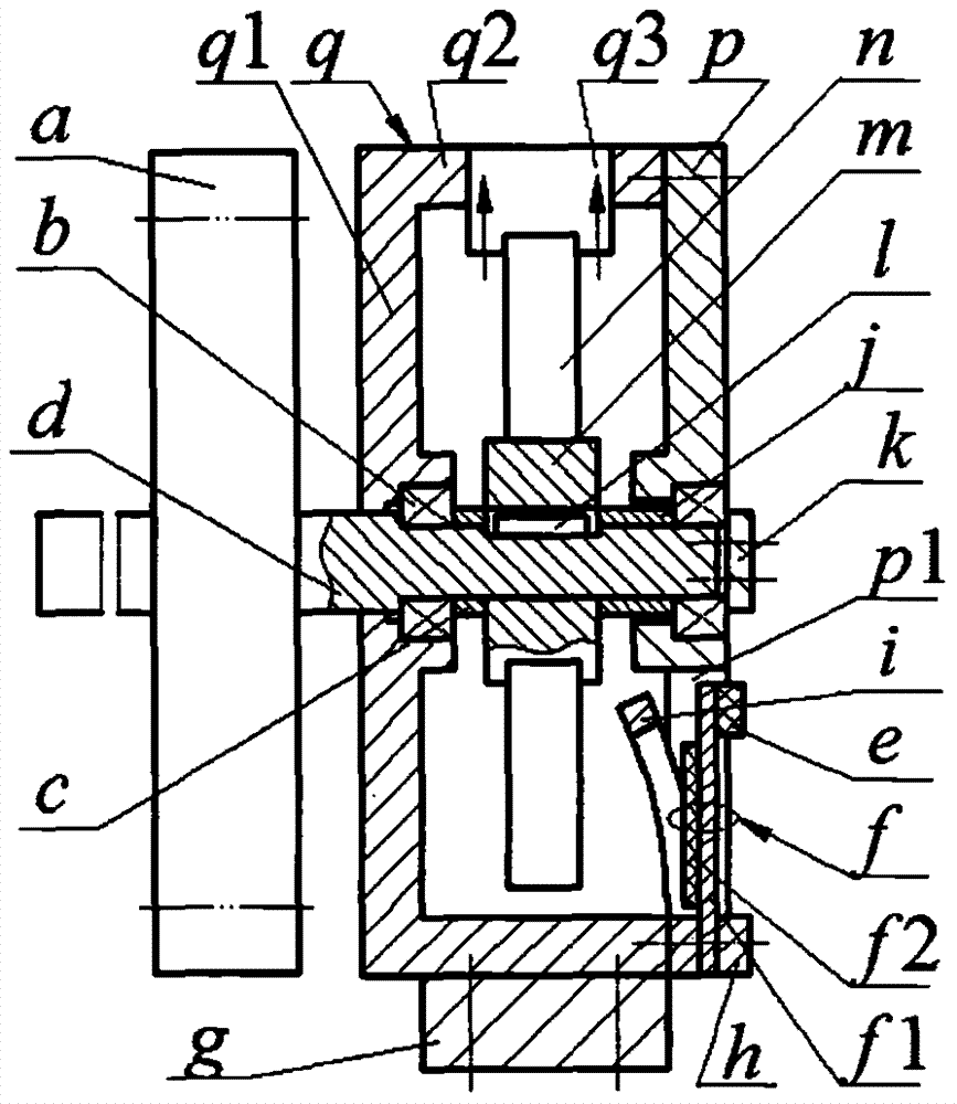
  • Figure 1
    Figure 1
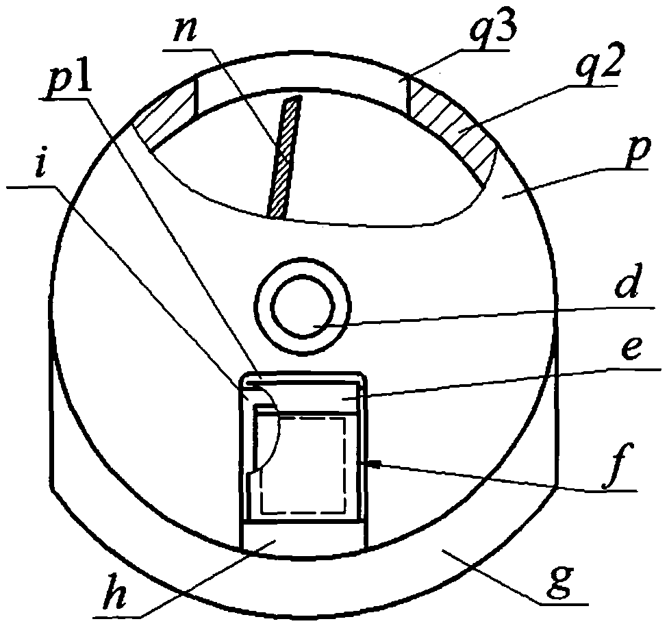
  • Figure 2
    Figure 2
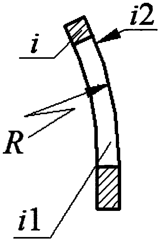
  • Figure 3
    Figure 3
Patent Text Reader

Abstract

The invention relates to a rotational flow excitation power generator used for supplying power to a wind power gearbox monitoring system, and belongs to the field of piezoelectric power generation. A shell, a left shaft sleeve, a wheel flange, a right shaft sleeve and a right wall plate having an inlet are arranged on a main shaft in a sleeving manner from left to right in sequence, wherein a baffle is mounted on the end part of the main shaft; the wheel flange and the main shaft are connected through a key; an outlet is formed in the cylinder wall of the shell; the end part of the cylinder wall of the shell is connected with the right wall plate; a balancing weight block is mounted outside the cylinder wall of the shell; a limiting frame, a piezoelectric vibrator and a pressing block are mounted on the end part of the cylinder wall of the shell in sequence; the limiting frame and the piezoelectric vibrator are arranged in the inlet of the right wall plate; a piezoelectric crystal plate is mounted close to the limiting frame; the length and the width of the piezoelectric crystal plate are less than that of the cavity of the limiting frame respectively; and the length and the width of a metal substrate are greater than that of the cavity of the limiting frame respectively. The rotational flow excitation power generator has the advantages and characteristics as follows: the piezoelectric vibrator is excited by the fluid motion caused by rotation, so that rigid impact and electromagnetic interference are avoided; the piezoelectric crystal plate only bears the pressure stress within a controllable range, so that high reliability is achieved; the rotational flow excitation power generator is not required to be fixed and supported; and the rotational flow excitation power generator can be applied to both of cantilever gear shafts and multi-gear coaxial occasions.
Need to check novelty before this filing date? Find Prior Art

Description

technical field

[0001] The invention belongs to the technical field of gear monitoring and piezoelectric power generation, and in particular relates to a swirl excitation generator used for power supply of a wind power gearbox monitoring system. Background technique

[0002] The gearbox is a key component of a wind turbine, and its function is to transmit power. When the wind turbine is running normally, the speed of the wind rotor is low, resulting in low efficiency of the generator. Therefore, it is necessary to increase the power generation capacity and efficiency through the gearbox. Because the wind power gearbox works in a variable speed and variable load environment, it is prone to failure; in addition, when the wind power gearbox fails, it is difficult to repair and the cost is high. The operation and maintenance cost of the wind power gearbox can be as high as 30% of the overall operating cost. Therefore, various forms of real-time monitoring systems and methods fo...

Examples

Embodiment Construction

[0013] The gear a is installed on the main shaft d, and the main shaft d is covered with a casing q, a left shaft sleeve c, a wheel rim m with blades n, a right shaft sleeve j, and a right wall plate p with an inlet p1 from left to right. , the end of the main shaft d is installed with a baffle k through screws; the wall plate q1 and the right wall p of the housing q are respectively sleeved on the main shaft d through the bearing b, and the inner ring of the bearing b on the wall plate q1 of the housing q The left side leans against the shaft shoulder of the main shaft d, the right side of the inner ring of the bearing b on the right wall plate p leans against the baffle k, and the wheel rim m and the main shaft d are connected by key 1; the cylinder of the housing q There is an outlet q3 on the wall q2, and the end of the cylinder wall q2 of the housing q is connected with the right wall plate p through screws, and a counterweight g is installed on the outside of the cylinder...