
A vehicle positioning tracking and collision alarm device

An alarm device, positioning and tracking technology, which is applied to the traffic control system, instruments, electrical components and other directions of road vehicles, can solve the problems of inability to use speed monitoring and theft tracking, the positioning system cannot continue to work, and the positioning device has a single function. The effect of controllable maximum stress, high reliability and strong environmental adaptability

Inactive Publication Date: 2017-11-21
ZHEJIANG NORMAL UNIVERSITY
View PDF5 Cites 0 Cited by
  • Summary
  • Abstract
  • Description
  • Claims
  • Application Information

AI Technical Summary

Problems solved by technology

However, the existing positioning device has a single function, and is mainly aimed at guiding the driver to the destination.
From a practical point of view, the vehicle positioning and tracking system can also realize functions such as real-time monitoring and reporting of vehicle speed, automatic alarm of major traffic accidents, or tracking of vehicle theft. The positioning system will no longer work; in addition, the existing positioning systems are external, can be artificially turned off or destroyed, and cannot be used for speed monitoring and theft tracking, etc.

Method used


Image

  • A vehicle positioning tracking and collision alarm device
  • A vehicle positioning tracking and collision alarm device
  • A vehicle positioning tracking and collision alarm device

Examples


Embodiment Construction

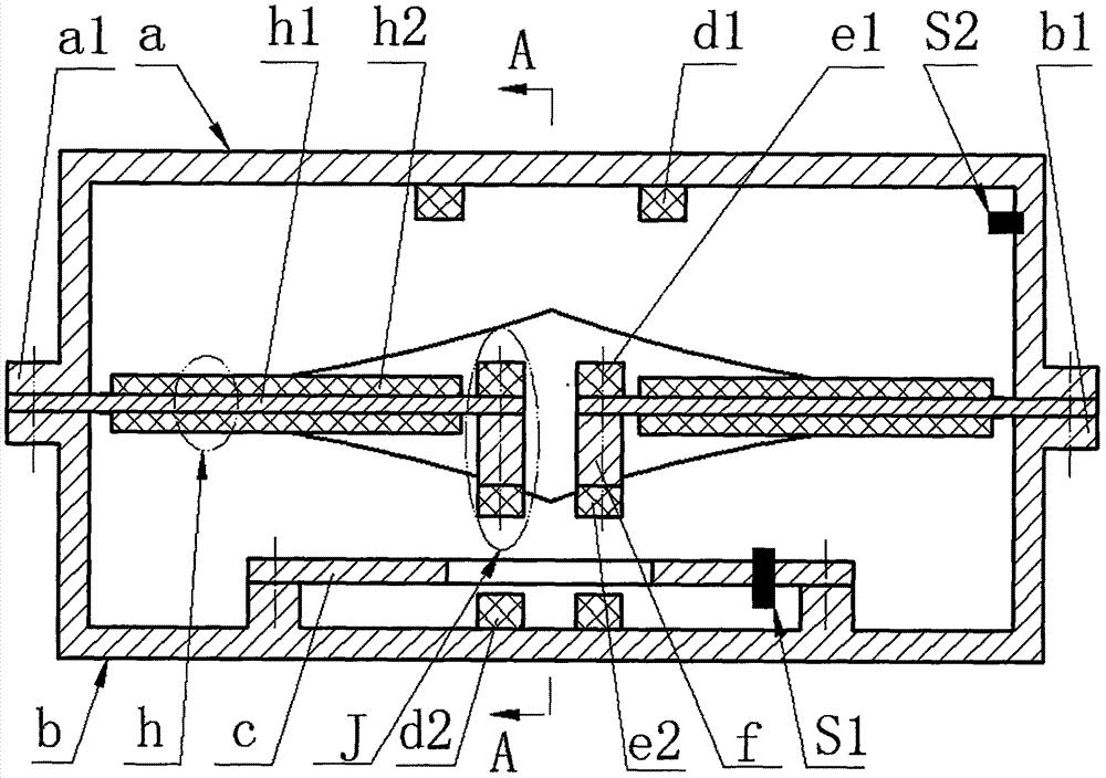
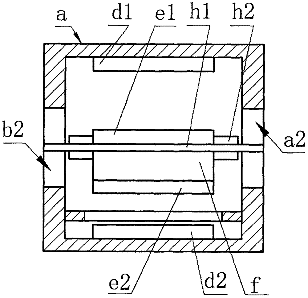
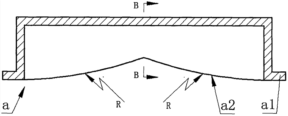
[0013] The left and right side walls of the upper shell a are provided with upper ear plates a1, and the ends of the front and rear side walls are provided with two upper limit surfaces a2. The left and right side walls of the lower shell b are provided with lower ear plates b1 and the front and rear sides. The ends of the walls are provided with two lower limit surfaces b2. The inner cavity of the upper shell a and the inner cavity of the lower shell b have the same length in the left and right direction and the width in the front and rear directions respectively. The left or right wall of the upper shell a The acceleration sensor S2 is installed on the upper wall, and the circuit board c with the transmitting unit S1 is installed on the bottom wall of the lower shell b by screws; the upper ear plate a1 and the lower ear plate b1 on the left and right sides are respectively connected by screws, and the left upper ear plate A cantilever-type metal substrate h1 is crimped between...


PUM


Abstract

The invention relates to a vehicle-mounted apparatus with functions of positioning, tracking and collision warning, and belongs to the electronic technical field of automobiles. Ear plates are arranged on the left and right side walls of upper and lower shells; limiting surfaces are arranged on the end parts of the front and back side walls; an acceleration sensor is arranged on the left side wall or the right side wall of the upper shell; a circuit board with an emission unit is arranged on the bottom wall of the lower shell; the upper and lower ear plates are connected through screws, and a cantilever beam type metal substrate is crimped between the upper and lower ear plates; the metal substrate, and piezoelectric wafers which are pasted on the upper and lower sides of the metal substrate form a piezoelectric vibrator; a moving magnet I and a mass block are arranged on the upper and lower sides at the free end of the metal substrate respectively; a moving magnet II is mounted at the lower end of the mass block; the moving magnet I, the mass block and the moving magnet II form an excitation arm; the width of the inner cavities of the upper and lower shells is less than that of the metal substrate, and greater than that of the piezoelectric wafers; and a fixed magnet I is mounted on the top wall of the upper shell while a fixed magnet II is mounted on the bottom wall of the lower shell. The vehicle-mounted apparatus with the functions of positioning, tracking and collision warning has the advantages and characteristics of high environmental adaptability, wide effective frequency band, high power generation capacity, and high reliability; and meanwhile, the vehicle-mounted apparatus can be used as an independent part to be embedded in a hidden place of the vehicle body, so that the vehicle-mounted apparatus is safe and reliable.

Description

Technical field [0001] The invention belongs to the technical field of automobile electronics, and specifically relates to a vehicle-mounted positioning tracking and collision warning device. Background technique [0002] Car positioning and navigation systems have been widely used in real life. However, the existing positioning device has a single function and is mainly aimed at guiding the driver to the destination. From a practical point of view, the on-board positioning and tracking system can also realize real-time monitoring and reporting of vehicle speed, automatic alarm for major traffic accidents, or vehicle stolen tracking functions, but because the existing positioning system uses the engine to supply power, when the engine is powered off or fails The positioning system will not continue to work; in addition, the existing positioning systems are all external, which can be turned off or destroyed artificially, and cannot be used for speed monitoring and theft tracking....

Claims


Application Information

Patent Timeline
Patent Type & Authority Patents(China)
IPC IPC(8): H02N2/18G08G1/00
CPCG08G1/205H02N2/186
Inventor 郑佳佳黄乐帅王淑云汪彬阚君武
Owner ZHEJIANG NORMAL UNIVERSITY
Learn More