
fuel pumping mechanism

A technology of pumping mechanism and fuel pump, applied in the direction of fuel injection pump, fuel injection device, pump, etc., can solve problems such as edge contact

Active Publication Date: 2018-09-18
DELPHI TECH IP LTD
View PDF4 Cites 0 Cited by
  • Summary
  • Abstract
  • Description
  • Claims
  • Application Information

AI Technical Summary

Problems solved by technology

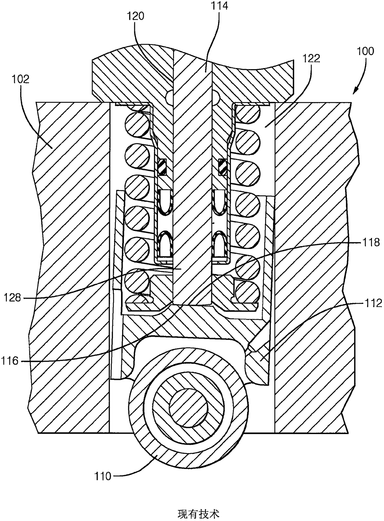
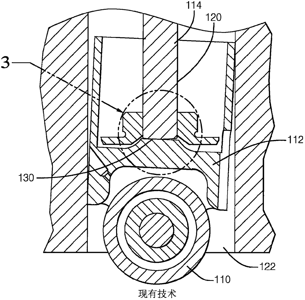
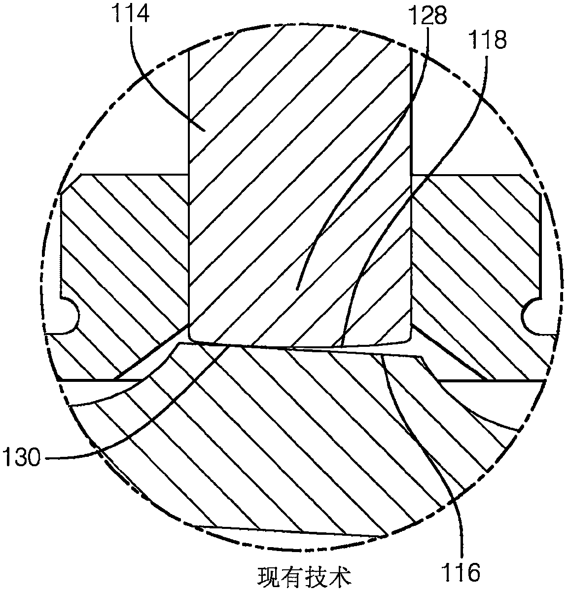
However, if the fillet is too large, edge contact will occur when lifter 112 tilts within lifter positioning hole 122

Method used


Image

  • fuel pumping mechanism
  • fuel pumping mechanism
  • fuel pumping mechanism

Examples


Embodiment Construction

[0018] refer to Figure 4 , the present invention includes a pumping mechanism 200 that includes a pump housing 202 . Pump housing 202 includes a plunger positioning bore 220 for positioning a pumping element in the form of plunger 214 , a drive mechanism including cam roller 210 , and an intermediate member including lifter 212 positioned in lifter positioning bore 222 .

[0019] The plunger locating bore 220 defines at one end a pumping chamber 224 into which a first end 226 of the plunger 214 extends.

[0020] Such as Figure 6 and Figure 8 As shown, the tappet 212 is provided with a plunger contact surface 218 ( Figure 6 ) contacting tappet contact surface 216. The figure represents a pumping stroke where the tappet contact surface 216 is in contact with the plunger contact surface 218 ie the load from the cam roller 210 is transferred via the contact surface 216 of the tappet 212 to the contact surface 218 of the plunger 214 . Accordingly, the plunger 214 is pushed...


PUM


Abstract

Internal combustion engine fuel pumping mechanism (200), comprising a pumping element (214) such as a plunger movable in a first positioning hole (220), an intermediate member (212) such as a tappet movable in a second positioning hole , and a drive mechanism such as a cam (210), wherein during the pumping stroke, the cam load is transferred to the plunger (214) via the plunger contact surface (218) and the tappet contact surface (216), the plunger contact surface (218 ) is radiused, and the tappet contact surface (216) is angled with respect to the axial axis of the tappet (212) at an angle selected so that when the cam load is applied, the tappet (212) is in the second locating hole When tilted inward, the contact surface of the tappet (212) is normal to the longitudinal axis of the second bore and plunger (214), thereby ensuring a substantially central point of contact between the contact surfaces. The inventive concept also extends to an intermediate member (212) comprising a contact surface (216) angled relative to the axial axis of the intermediate member (212).

Description

technical field [0001] The present invention relates to a fuel pump for use in an internal combustion engine, and more particularly to an improved pumping mechanism for a fuel pump having at least one pumping element driven by an engine driven cam or other suitable drive means. Background technique [0002] figure 1 is a partial sectional view of a pumping mechanism according to the prior art. As shown in this figure, a general pumping mechanism 100 for a fuel pump for an internal combustion engine includes a pump housing 102 containing a pumping element positioning aperture 120 within which a pumping element such as a plunger 114 can move. A first end (not shown) of plunger 114 extends into a pumping chamber (not shown) defined at one end of pumping element positioning bore 120 . The pumping mechanism 100 further includes a drive mechanism such as a cam roller 110 and an intermediate member such as a follower or lifter 112 movable within an intermediate member positioning...

Claims


Application Information

Patent Timeline
Patent Type & Authority Patents(China)
IPC IPC(8): F02M59/10
CPCF02M59/102F04B1/14F04B9/04
Inventor C·麦克林德尔
Owner DELPHI TECH IP LTD
Learn More