Tripod-type constant velocity joint

A constant velocity joint and three-ball pin technology, applied in the field of quick joints, can solve problems such as limitation and deviation, achieve effective wear characteristics, reduce operating noise, and achieve the effect of maintenance

Active Publication Date: 2016-11-09
NTN CORP
View PDF6 Cites 1 Cited by
  • Summary
  • Abstract
  • Description
  • Claims
  • Application Information

AI Technical Summary

Problems solved by technology

[0010] However, according to the constant velocity joint of Patent Document 1, a so-called deflection (curvature) occurs in a state where the axis centers of the drive shaft and the driven shaft intersect near the joint portion where the constant velocity joint is disposed with respect to the non-parallel axis. ) state, it is also easy to correspond to a relatively large deviation
[0011] However, there is a state that the extension line of the axis center of the drive shaft and the axis center of the driven shaft intersect at a part other than the joint part, or the axis center of the drive shaft and the axis center of the driven shaft are parallel and do not intersect. In the state of the so-called eccentric state, the range of deviation that can be handled is limited

Method used


Image

  • Tripod-type constant velocity joint
  • Tripod-type constant velocity joint
  • Tripod-type constant velocity joint

Examples


no. 1 approach

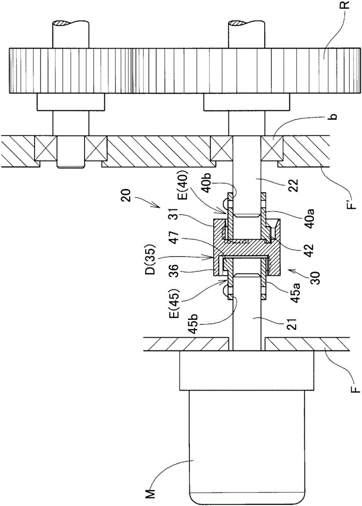
[0080] figure 1 Main parts of the rotation transmission mechanism using the tripod type constant velocity joint according to the first embodiment of the present invention are shown.

[0081] This rotation transmission mechanism includes: a rotating part R having a gear involved in the transmission of driving force, a driving source M constituted by a motor that rotates the rotating part R around an axis, and a mechanism for transmitting the driving force from the driving source M to the rotating part R. Drive transmission device 20 .

[0082] The drive transmission device 20 is provided with a tripod type constant velocity shaft connected by a drive shaft 21 extending from the drive source M and a driven shaft 22 extending from the rotation part R (hereinafter referred to as "rotation body shaft 22"). The connection unit 30 constituted by joints. The connecting unit 30 has the function of suppressing the state that the axis center of the rotating body shaft 22 and the axis c...

no. 2 approach

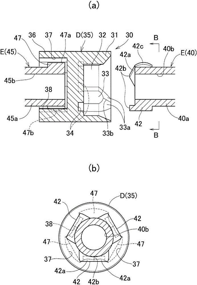
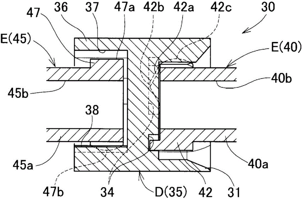
[0113] Figure 7 A second embodiment is shown. The coupling unit 30 of this embodiment is constituted by an intermediate member D and shaft end members E provided on the drive shaft 21 side end and the driven shaft 22 side end of the intermediate member D, respectively. Here, for the intermediate member D, the outer ring 31 is on either side in the axial direction, and the tripod member 45 is on the other side. For the shaft end member E, the side where the above-mentioned outer ring 31 is provided is the tripod member. In the pin member 40 , the side where the tripod member 45 is provided is the outer ring 36 .

[0114] The connection structure of the connection part on one axial side of the intermediate part D, that is, the outer ring 31 and the corresponding tripod part 40, and the connection part on the other side in the axial direction, that is, the outer ring 36 and the corresponding tripod part The connection structure of 45 is the same as that of the above-mentioned ...

no. 3 approach

[0119] Figure 8 Main parts of the rotation transmission mechanism of the tripod type constant velocity joint of the present invention using the third embodiment of the present invention are shown.

[0120] This rotation transmission mechanism includes: a rotating part R having a gear involved in the transmission of driving force, a driving source M constituted by a motor that rotates the rotating part R around an axis, and a mechanism for transmitting the driving force from the driving source M to the rotating part R. Drive transmission device 20 .

[0121] The drive transmission device 20 is provided with a tripod type constant velocity shaft connected by a drive shaft 21 extending from the drive source M and a driven shaft 22 extending from the rotation part R (hereinafter referred to as "rotation body shaft 22"). The connection unit 30 constituted by joints. The connection unit 30 has the function of suppressing the state that the axis center of the rotating body shaft 2...


PUM


Abstract

A tripod-type constant velocity joint that couples a drive shaft (21) and a driven shaft (22) and uses tripod members (40, 45) as a coupling means (30) that: suppresses rotation speed fluctuation of the driven shaft (22) that occurs when the angle between the axis of the drive shaft (21) and the axis of the driven shaft (22) is other than 180 degrees or when a misalignment occurs, and transmits the rotation of the drive shaft (21) to the driven shaft (22); and couples the drive shaft (21) and the driven shaft (22). The tripod members (40, 45) have an intermediate member (D) and shaft end members (E) provided at both ends thereof arranged therein. The intermediate member (D) has both end surfaces open in the axial direction and has outer rings (31, 36) having formed therein track grooves (32, 37) that extend in the axial direction on the inner circumference and have an interval of 120 degrees therebetween in the circumference direction. The shaft end members (E) each have three protrusions (42, 47) housed inside each track groove (32, 37) so as to be slidable in the axial direction.

Description

technical field [0001] The invention relates to a constant velocity joint that connects a drive shaft and a driven shaft, and transmits the power of the drive shaft to the driven shaft. Background technique [0002] Conventionally, a constant velocity joint is known as a member that transmits rotational torque of a drive shaft of an automobile to an axle. [0003] The constant velocity joint is a component that maintains the constant velocity of the drive shaft and the driven shaft and allows the angular displacement of the two shafts. Therefore, it is also widely used in various industrial machinery, home appliances, and enterprise equipment other than automobiles. [0004] As constant velocity joints, there are fixed type constant velocity joints allowing only angular displacement and sliding type constant velocity joints allowing angular displacement and axial displacement. As such sliding type constant velocity joints, a joint described in Patent Document 1 below is know...

Claims


Application Information

Patent Timeline
Patent Type & Authority Applications(China)
IPC IPC(8): F16D3/205F16D3/20
CPCF16D3/2055F16D3/72
Inventor 福泽觉山冈贤二藤塚郁马
Owner NTN CORP
Why Eureka
Try Eureka