Supercharge Your Innovation With Domain-Expert AI Agents!

Capacitive level sensor circuit

A water level detection circuit, capacitive technology, applied in measurement devices, liquid/fluid solids measurement, liquid level indicators for physical variable measurement, etc., can solve problems such as reduced reliability and durability, incorrect operation, and shortened component life. , to achieve the effect of preventing detection action and chattering, stable circuit operation and improving reliability

Active Publication Date: 2016-11-09
KEUMYANG IND
View PDF9 Cites 0 Cited by
  • Summary
  • Abstract
  • Description
  • Claims
  • Application Information

AI Technical Summary

Problems solved by technology

[0004] However, the slight shaking of the liquid stored in the main body of the container is also likely to cause the water surface to sway. Therefore, the capacitive water level detector in the prior art repeatedly detects the water level in a very short period of time, and the vibration phenomenon will inevitably occur.
[0005] Therefore, the capacitive water level detectors in the prior art cause erroneous operation due to unnecessary frequent detection actions and vibration phenomena, shortening the life of components, thereby reducing reliability and durability

Method used


Image

  • Capacitive level sensor circuit
  • Capacitive level sensor circuit
  • Capacitive level sensor circuit

Examples


no. 1 example

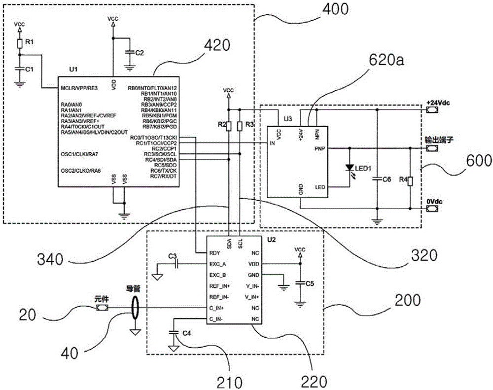
[0035] figure 2 It is a circuit diagram showing the capacitive water level detection circuit of the first embodiment of the present invention.

[0036] If the sensor rod 20 and the conduit 40 are located outside the liquid level, the first control unit 220 transmits the low signal to the second control unit 420 through the SCL and SDA ports as synchronous serial communication ports, and the second control unit 420 transmits the low signal through the output port. The signal is transmitted to the third control unit 620a, and the third control unit 620a outputs a low signal through the PNP output port and transmits it to the external output terminal (OUTPUT).

[0037]Therefore, according to the capacitance of the liquid level sensor rod 20 and the conduit 40 changes, the first control unit 220 compares the capacitance with the capacitor 210, and when the capacitance measured by the sensor rod 20 and the conduit 40 is smaller than the capacitance of the capacitor 210 , the firs...

no. 2 example

[0041] image 3 It is a circuit diagram showing the capacitive water level detection circuit of the second embodiment of the present invention.

[0042] In the second embodiment, because the output port of the third control unit 620b is of NPN type, only the output signal is opposite to that of the first embodiment described above, and the rest of the structure is the same or very similar, so it will not be repeated here.

no. 3 example

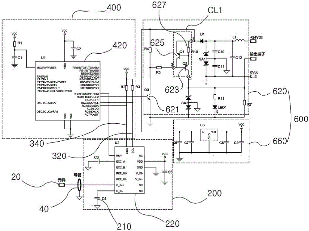
[0044] Figure 4 It is a circuit diagram showing the capacitive water level detection circuit of the third embodiment of the present invention.

[0045] If the sensor rod 20 and the conduit 40 are located outside the liquid level, the first control unit 220 transmits a low signal to the second control unit 420 through the SCL and SDA ports as synchronous serial communication ports, and the low signal of the second control unit 420 is output to The base terminal of the first transistor 621 of NPN type, and the collector terminal of the above-mentioned first transistor 621 is applied with the base terminal of the second transistor 623 of PNP type in a high state, and the above-mentioned second transistor The emitter terminal of the 623 outputs a low signal.

[0046] According to the change of the capacitance of the water level sensor rod 20 and the conduit 40 of the liquid, the first control unit 220 compares the capacitance of the capacitor 210, and when the capacitance measur...


PUM


Abstract

The present invention relates to a capacitive level sensor circuit. The capacitive level sensor circuit for preventing unnecessary and frequent sensing and chattering due to the sloshing of a liquid, according to one embodiment of the present invention, is applied to a capacitive level sensor, which comprises a sensor rod forming a first electrode and a hollow guard pipe separately accommodating a part of the sensor rod and forming a second electrode, and is integrated into a circuit board provided inside the guard pipe and measures a liquid level by sensing a variation in capacitance via the first and second electrodes. The capacitive level sensor circuit comprises: a sensor circuit unit which comprises a capacitor having a predetermined amount of capacitance and a first control unit for comparing the capacitance of the capacitor and the capacitance measured via the first and second electrodes and outputting a high or low signal, and which has multiple communication ports having a clock line and a data line respectively connected thereto; a delay circuit unit, which is connected in parallel to the first control unit via the clock line and the data line and outputs a high or low signal after a predetermined delay time according to the output signal of the first control unit; and an output circuit unit for transmitting a high or low signal to an external output terminal according to the output signal of the delay circuit unit and receiving a DC voltage for circuit operation.

Description

technical field [0001] The invention relates to a capacitive water level detection circuit, in particular to a capacitive water level detection circuit which uses the capacitance difference between a part submerged in a liquid and a part not submerged to detect the water level. Background technique [0002] The technique of measuring the water level of a liquid has been developed from a float instrument method and a magnet instrument method to an electronic instrument method. A superficial example of the electronic water level measurement method is the capacitive method, which is the best method capable of solving both the error rate and the defect rate of the floating instrument method or the magnet instrument method. [0003] The above-mentioned capacitive water level detector has attracted attention in terms of precision and economy, such as figure 1 As shown, it includes: container main body 1, which is used to store liquid and whose outer wall constitutes an external e...

Claims


Application Information

Patent Timeline
IPC IPC(8): G01F23/26
CPCG01F23/266G01F23/268
Inventor 郑庆镇
Owner KEUMYANG IND
Features
  • R&D
  • Intellectual Property
  • Life Sciences
  • Materials
  • Tech Scout
  • Unparalleled Data Quality
  • Higher Quality Content
  • 60% Fewer Hallucinations
Learn More