Feeding device of multi-head sawing machine for pipe

A technology for feeding devices and pipes, applied in the direction of sawing machine devices, metal sawing equipment, metal processing equipment, etc., can solve the problems of long time consumption of pipes, low sawing efficiency, high cost of sawing machines, etc., to achieve convenient material retrieving and convenient The effect of accurate feeding and shortening the sawing time

Active Publication Date: 2016-11-16
SUZHOU KINKALTECK MACHINERY TECH
View PDF8 Cites 8 Cited by
  • Summary
  • Abstract
  • Description
  • Claims
  • Application Information

AI Technical Summary

Problems solved by technology

[0002] The sawing principle of the current multi-head sawing machine is the same as that of the single-head saw, which is to combine multiple sawing heads on one device, and use the clamping device to correspond to the sawing heads one by one. After the clamping device clamps the pipe, Then use the saw blade of the saw head to saw the pipe, but this multi-head sawing machine has the following disadvantages: 1. The sawing efficiency is low, and it needs feeding, feeding, and clamping action of the clamping device, and then the saw blade The actions of feeding, retracting, releasing the clamping device, and discharging each action need to be realized by a separate mechanism, so sawing a pipe takes a long time and the efficiency is very low; 2. This kind of sawing machine The cost is high, because each step of sawing requires a corresponding device or mechanism to realize the action, therefore, the equipment investment cost is high and the volume is large; 3. Because this kind of multi-head sawing machine first needs a clamping mechanism to clamp Therefore, the shortest distance for sawing pipes cannot be made shorter due to the influence of the clamping mechanism. The clamping mechanism limits the shortest limit length of the pipes sawed by the multi-head saw

Method used


Image

  • Feeding device of multi-head sawing machine for pipe
  • Feeding device of multi-head sawing machine for pipe
  • Feeding device of multi-head sawing machine for pipe

Examples


Embodiment Construction

[0025] The present invention will be described in further detail below through specific examples.

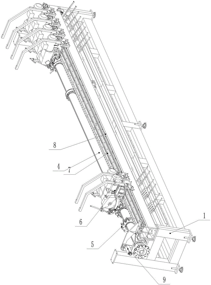
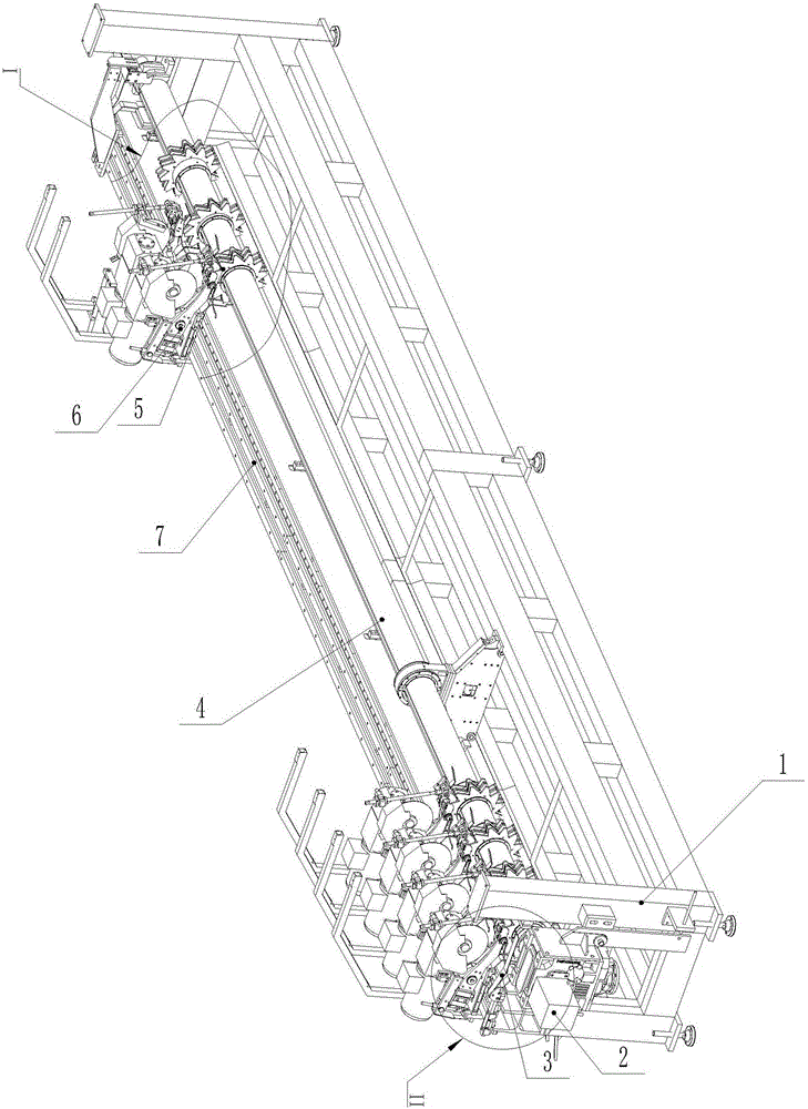
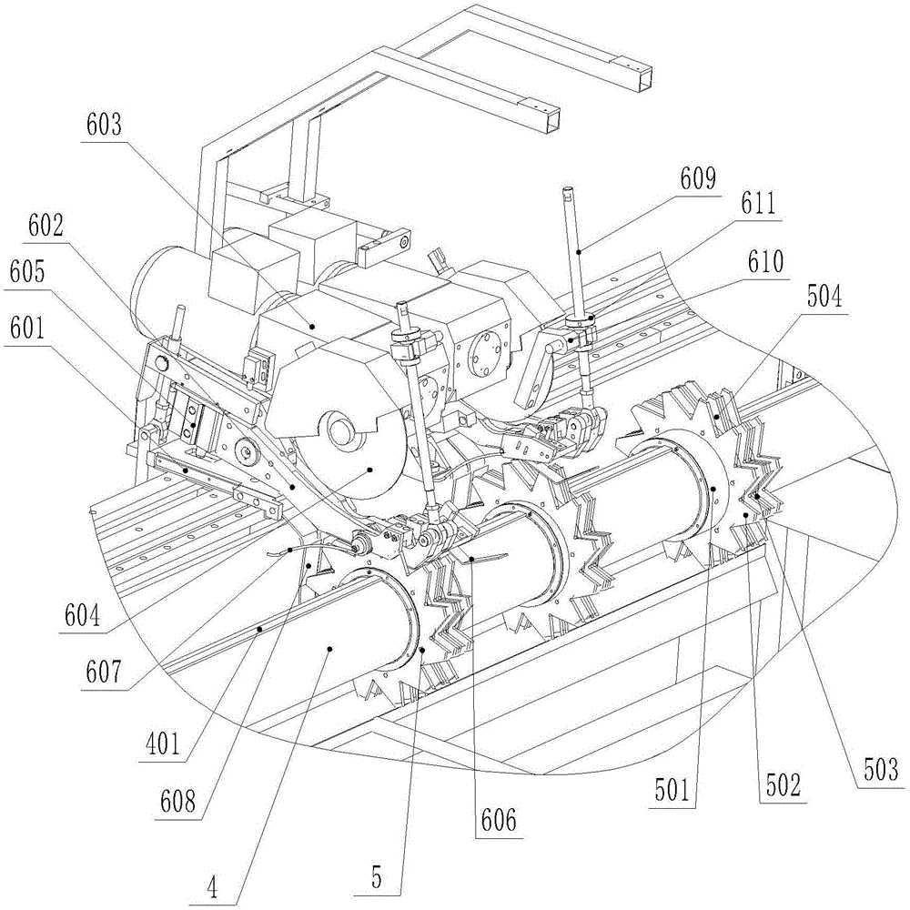
[0026] Such as Figure 1 to Figure 5 As shown, a feeding device of a pipe multi-head sawing machine includes a frame 1 on which a feed spindle 4 is rotatably installed, and the feed spindle 4 is driven by a rotary feed power device 2, and the rotation The feed power device 2 is driven by a reduction motor. The feed spindle 4 is equipped with several dial gear sets 5, and the dial gear sets 5 are provided with a dial tooth groove 503 arranged in a circle. The position of material gear set 5 is corresponding to the position of sawing head 6 that is arranged on the frame 1, and described material setting gear set 5 is provided with the feed gap 504 that facilitates saw blade 604 to enter, and the depth of this feed gap 504 is greater than The pipe diameter of the pipe material; the automatic feeding device on the upstream side of the rotation of the shifting gear set 5 is connecte...


PUM


Abstract

The invention discloses a feeding device of a multi-head sawing machine for a pipe. The feeding device of the multi-head sawing machine for the pipe comprises a machine frame; a feeding main shaft is rotatably mounted on the machine frame and is driven by a rotating feeding power device; a plurality of material poking gear sets are mounted on the feeding main shaft; a material poking tooth groove is circumferentially formed in each of the material poking gear sets; the positions of the material poking gear sets correspond to the positions of sawing heads on the machine frame; a feeding clearance which facilitates the entrance of a saw blade is formed in each material poking gear set; the depth of each feeding clearance is greater than the pipe diameter of the pipe; and the rotating upstream side of each material poking gear set is connected with an automatic feeding device. According to the feeding device, feeding, sawing feeding and discharging can be completed quickly, so that the sawing time is greatly shortened, and the sawing efficiency is improved.

Description

technical field [0001] The invention relates to a feeding device, in particular to a feeding device of a pipe multi-head sawing machine. Background technique [0002] The sawing principle of the current multi-head sawing machine is the same as that of the single-head saw, which is to combine multiple sawing heads on one device, and use the clamping device to correspond to the sawing heads one by one. After the clamping device clamps the pipe, Then use the saw blade of the saw head to saw the pipe, but this multi-head sawing machine has the following disadvantages: 1. The sawing efficiency is low, and it needs feeding, feeding, and clamping action of the clamping device, and then the saw blade The actions of feeding, retracting, releasing the clamping device, and discharging each action need to be realized by a separate mechanism, so sawing a pipe takes a long time and the efficiency is very low; 2. This kind of sawing machine The cost is high, because each step of sawing re...

Claims


Application Information

Patent Timeline
Patent Type & Authority Applications(China)
IPC IPC(8): B23D45/12B23D47/04
CPCB23D45/12B23D47/042
Inventor 柯晓华
Owner SUZHOU KINKALTECK MACHINERY TECH
Why Eureka
Try Eureka