
A knife advance and retreat mechanism for end surface bevel processing equipment

A technology of bevel processing, advancing and retreating knives, applied in the direction of metal processing equipment, metal processing machine parts, manufacturing tools, etc., can solve the problem that the bevel gear assembly is easy to be damaged, the guide block is difficult to process and manufacture, and the universal coupling cannot be rigid. Transmission and other issues, to achieve the effect of maintaining axial stability and improving the efficiency of groove processing

Active Publication Date: 2018-08-14
HUAHENG WELDING
View PDF5 Cites 0 Cited by
  • Summary
  • Abstract
  • Description
  • Claims
  • Application Information

AI Technical Summary

Problems solved by technology

Among them, the guide block of the square guide mechanism is difficult to manufacture, and the symmetry and parallelism are difficult to guarantee, which directly affects the accuracy of the knife advance and retreat; the bevel gear advance and retreat mechanism uses two bevel gears to achieve the function of right-angle reversing, and needs to be set. Connect the drive shaft to the coupling to realize the function of advancing and retracting the knife
However, during the cutting process, the universal coupling cannot perform rigid transmission, and the cutting force repeatedly impacts the bevel gear. The bevel gear assembly is easily damaged, and the replacement and maintenance are more complicated, which affects production.
[0003] In addition, the Chinese patent CN104786088 A discloses a beveling machine advance and retreat mechanism, which uses a rack and pinion to cooperate to realize the advance and retreat knife, but the beveling machine using the above-mentioned advance and retreat mechanism can only use single-blade cutting. For pipes, the processing time is long and the efficiency is low

Method used


Image

  • A knife advance and retreat mechanism for end surface bevel processing equipment
  • A knife advance and retreat mechanism for end surface bevel processing equipment
  • A knife advance and retreat mechanism for end surface bevel processing equipment

Examples


Embodiment Construction

[0027] The present invention will be described in detail below with reference to the embodiments shown in the accompanying drawings. However, this embodiment does not limit the present invention, and any structural, method, or functional changes made by those skilled in the art according to this embodiment are included in the protection scope of the present invention.

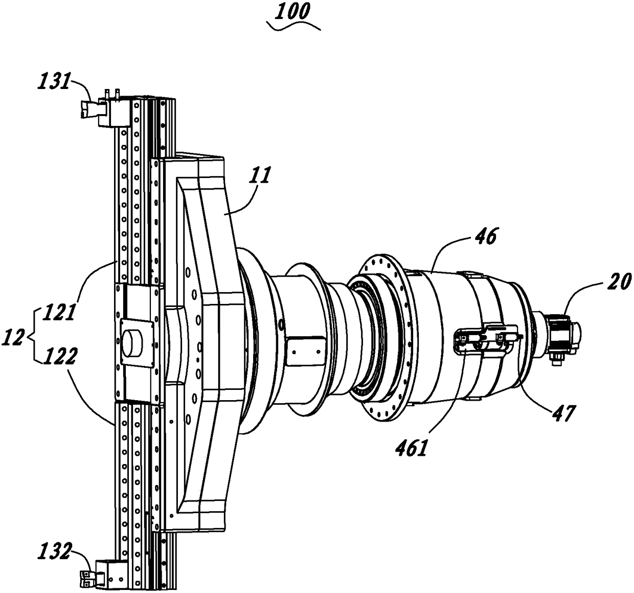
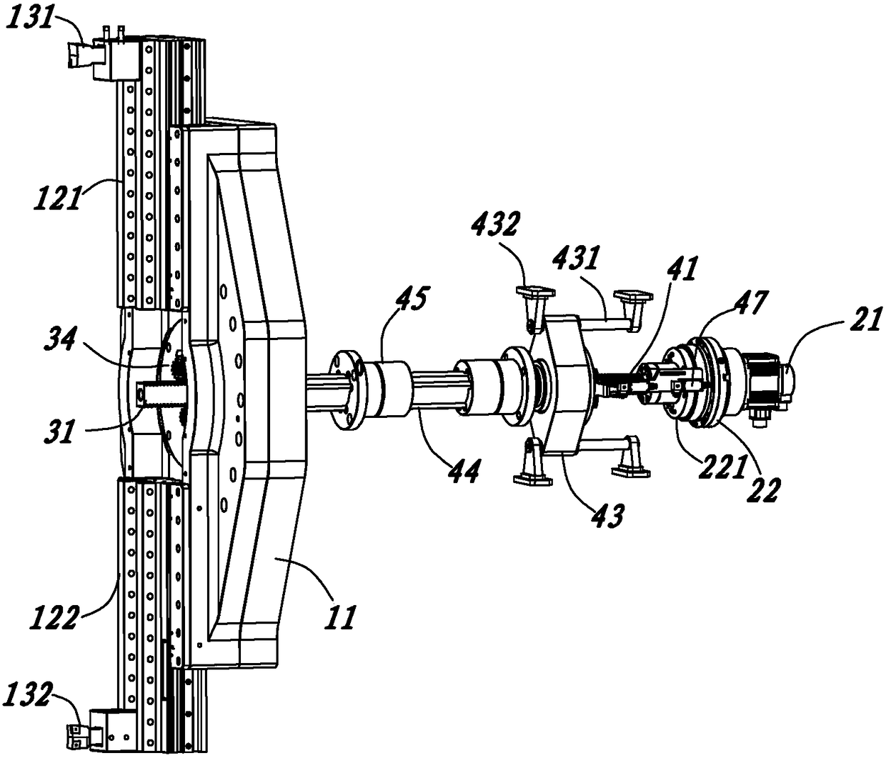
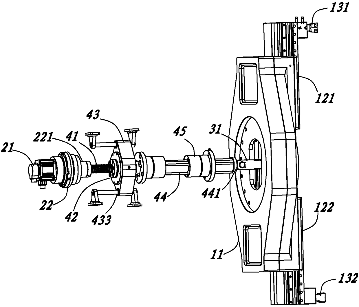
[0028] see Figure 1 to Figure 11 Shown is a preferred embodiment of the present invention. Such as figure 1 As shown, the advancing and retracting mechanism 100 includes a cutterhead 11 , a cutter seat 12 mounted on the front side of the cutter head 11 , and a driving assembly 20 for driving the cutter seat 12 to move radially of the cutter head 11 . Wherein, the knife seat 12 includes a first knife seat 121 and a second knife seat 122 arranged symmetrically along the center of the cutter head 11, and the first knife seat 121 and the second knife seat 122 are respectively used for installation and slope The...


PUM


Abstract

A tool feeding and relieving mechanism used for an end face groove preparation device comprises a cutter, a tool apron and a drive assembly for driving the tool apron to move in the radial direction of the cutter. The tool apron comprises a first tool apron body and a second tool apron body. The tool feeding and relieving mechanism further comprises an axial double-faced rack, a first gear, a second gear, a first radial rack and a second radial rack, wherein the axial double-faced rack extends forwards and backwards and penetrates the center position of the tool apron; the first gear and the second gear are fixed to the tool apron and are engaged with the two sides of the axial double-faced rack correspondingly; the first radial rack is connected with the first tool apron body and engaged with the first gear; and the second radial rack is connected with the second tool apron body and engaged with the second gear. The rear end of the axial double-faced rack is connected to the drive assembly and is driven by the drive assembly to move forwards and backwards so that the synchronous movement of the first tool apron body and the second tool apron body in the radial direction of the cutter can be driven. According to the tool feeding and relieving mechanism, the groove preparation efficiency is effectively improved through double-tool cutting, the feed speed of the tool apron can be controlled in real time, and the tool feeding and relieving mechanism is more suitable for groove preparation of pipes with thick pipe walls.

Description

technical field [0001] The invention relates to the technical field of pipe bevel processing equipment, in particular to an advancing and retreating knife mechanism of end face bevel processing equipment. Background technique [0002] The advance and retreat knife mechanism of the existing pipeline end face beveling machine includes a square guide mechanism, a bevel gear advance and retreat knife mechanism, and the like. Among them, the guide block of the square guide mechanism is difficult to manufacture, and the symmetry and parallelism are difficult to guarantee, which directly affects the accuracy of the knife advance and retreat; the bevel gear advance and retreat mechanism uses two bevel gears to achieve the function of right-angle reversing, and needs to be set. Connect the drive shaft to the coupling to realize the function of advancing and retreating the knife. However, during the cutting process, the universal coupling cannot perform rigid transmission, and the cu...

Claims


Application Information

Patent Timeline
Patent Type & Authority Patents(China)
IPC IPC(8): B23Q5/40
CPCB23Q5/40
Inventor 卜千根汪魁汪忠
Owner HUAHENG WELDING
Learn More