Truss robot multisection cross beam horizontal adjusting device

A truss robot and level adjustment technology, applied in the direction of manipulators, manufacturing tools, etc., can solve the problems of increased cost, uncoordinated appearance, small contact surface, etc., and achieve the effects of improving installation performance, facilitating promotion and use, and increasing contact surface

Active Publication Date: 2016-11-16
湖北火爆机器人科技有限公司
View PDF6 Cites 3 Cited by
  • Summary
  • Abstract
  • Description
  • Claims
  • Application Information

AI Technical Summary

Problems solved by technology

[0005] At present, some domestic truss robot companies basically use thick and thin bolts to adjust the horizontal and vertical adjustment of multi-section truss beams, but there are several shortcomings: First, the thick bolts jack up the square steel beams, and the contact surface is small, even in the thick bolt holes. Install the locking bolt, because the contact surface is small, the shaking or instability will increase during the walking of the truss robot, and it cannot be used for a long time
Second, the appearance is ugly. Because the bolts need to be adjusted and screwed, they cannot be painted. At present, most of them are blackened, which is inconsistent with the appearance and color matching of the entire truss robot, and the appearance grade cannot be improved.
The third is that the square steel and the upper end of the column need to add an adjustment plate, the appearance is not coordinated, and the cost is increasing, which is not the best technical solution

Method used


Image

  • Truss robot multisection cross beam horizontal adjusting device
  • Truss robot multisection cross beam horizontal adjusting device
  • Truss robot multisection cross beam horizontal adjusting device

Examples


Embodiment Construction

[0021] The technical solution of the present invention will be further described below in conjunction with the accompanying drawings.

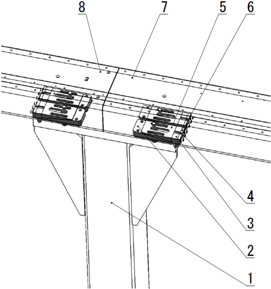
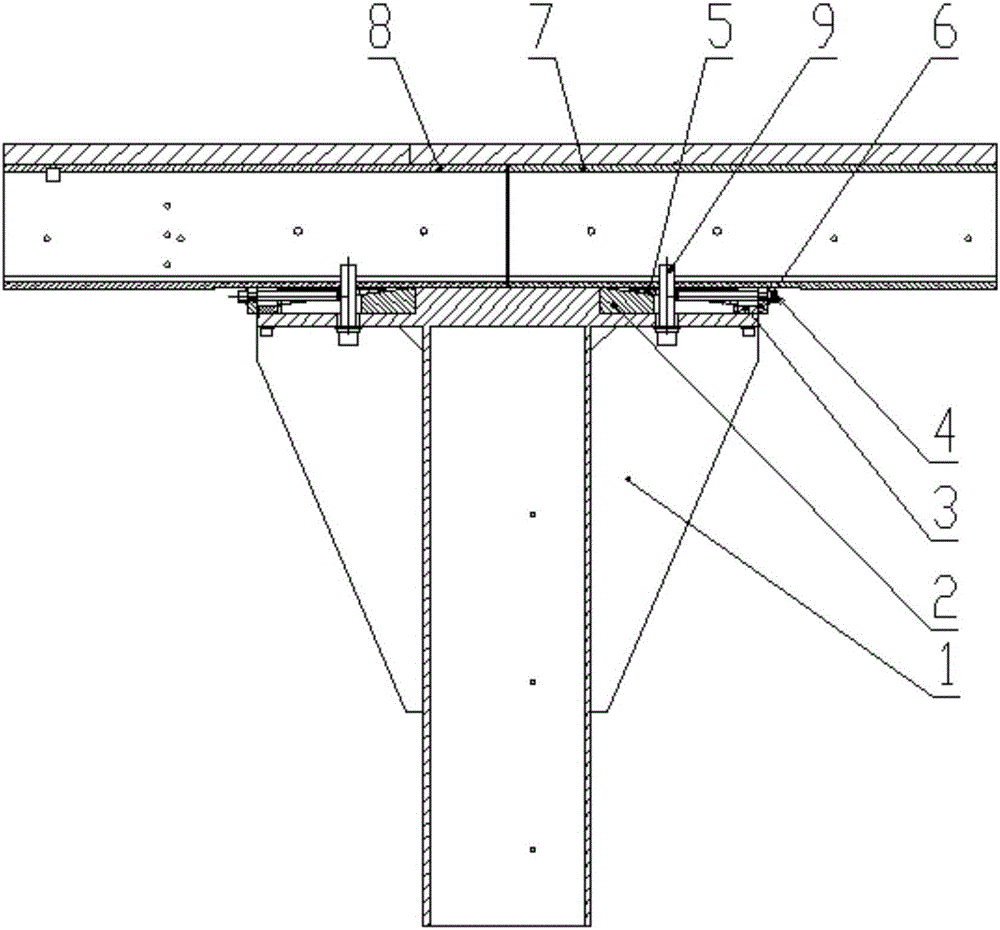
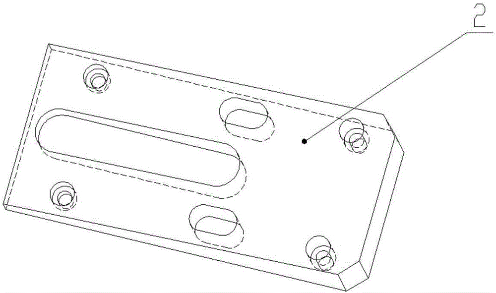
[0022] Such as Figure 1 to Figure 7 As shown, the multi-section crossbeam level adjustment device of the present invention includes a truss column 1, an inclined plane fixed block 2, a large notch fixed stop 3, an adjusting bolt 4, an inclined plane adjustment block 5, and a small notch fixed stop 6. Such as image 3 and Figure 6 As shown, the top of the inclined plane fixing block 2 of the present invention is provided with an upper inclined plane, and the bottom of the inclined plane adjusting block 5 is provided with a lower inclined plane, and the upper inclined plane is consistent with the inclination of the lower inclined plane. After the upper slope, the plane of the top of the slope adjustment block 5 is in a device parallel to the slope of the slope fixed block 2 bottoms.

[0023] Such as figure 1 , figure 2 As shown, in the p...


PUM


Abstract

The invention relates to the field of leveling of multisection cross beams, in particular to a truss robot multisection cross beam horizontal adjusting device. An upper inclined surface is arranged at the upper part of an inclined surface fixed block; a lower inclined surface is arranged at the lower part of an inclined surface adjusting block; the upper inclined surface and the lower inclined surface are consistent in inclination; the inclined fixed block is fixed at the upper part of a truss stand column; the inclined surface adjusting block is put on the upper inclined surface of the inclined surface fixed block; the upper inclined surface of the inclined surface fixed block is contacted and mounted with the lower inclined surface of the inclined surface adjusting block; a large notch fixed stopper is fixed in a groove formed in the upper part of the truss stand column; a small notch fixed stopper is fixed on the side surface of the large notch fixed stopper; an adjusting bolt and the inclined surface adjusting block are horizontally connected through a thread; and a ring notch of the adjusting bolt is clamped in a U-shaped groove of the small notch fixed stopper. The device realizes horizontal adjustment of multisection cross beams among all truss stand columns, and has such characteristics as long service life, beautiful appearance, simple structure and low cost.

Description

technical field [0001] The invention relates to the field of multi-segment beam leveling, in particular to a multi-segment beam level adjustment device for a truss robot. Background technique [0002] At present, in industrial automation production, the automatic connection between machine tools is developing in the direction of truss robots, but most trusses only solve the automatic connection between two to three machine tools. Long-stroke truss robots are rare in the market, which is mainly affected by It is limited to long-stroke truss robot beam processing and difficult installation, which leads to high cost of long-stroke truss robot. [0003] Due to the difficulty of multi-stage assembly of long-stroke trusses, the beams of short-stroke trusses currently on the market mainly use one square steel or two square steels to be spliced ​​and installed on the columns. The adjustment of one or two beams is relatively simple, but multiple The splicing of square steel tends to...

Claims


Application Information

Patent Timeline
Patent Type & Authority Applications(China)
IPC IPC(8): B25J19/00
CPCB25J19/00
Inventor 张伟张璐
Owner 湖北火爆机器人科技有限公司
Why Eureka
Try Eureka