Truss robot

A truss robot and column technology, which is applied in the field of truss robots, can solve the problems of poor balance adjustment of truss robots, poor clamping, and lack of lubrication at the teeth meshing.

Pending Publication Date: 2019-03-19
浙江勃展工业自动化设备有限公司
View PDF0 Cites 3 Cited by
  • Summary
  • Abstract
  • Description
  • Claims
  • Application Information

AI Technical Summary

Problems solved by technology

The defects of the existing truss robot are: 1. The workpiece chuck of the lathe is set horizontally, and it is difficult to place the workpiece in place when the workpiece is placed on the workpiece chuck, resulting in u

Method used


Image

  • Truss robot
  • Truss robot
  • Truss robot

Examples


Embodiment Construction

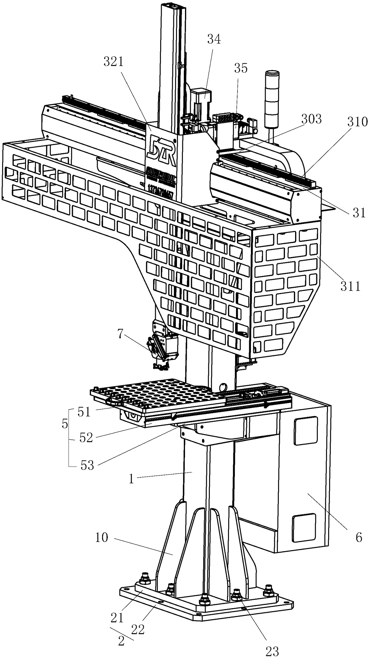
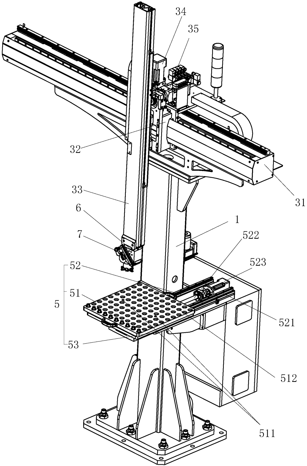
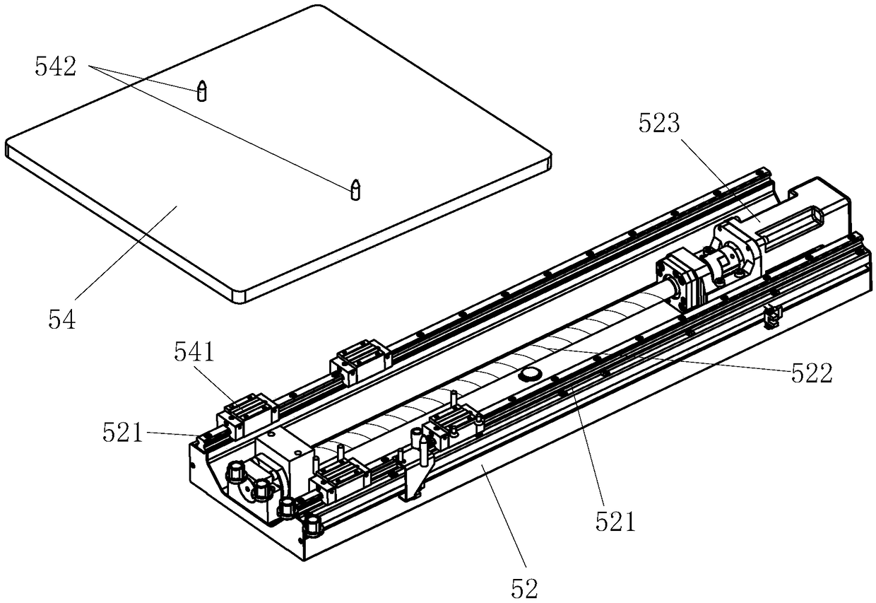
[0035] refer to Figure 1 to Figure 20 It can be seen that the present invention: a truss robot, including a column 1, a base 2 located at the upper and lower ends of the column 1, and a vertical and horizontal movement assembly 3, and the column 1 is sequentially provided with an oil pump 41, an oil storage tank 4, and a pallet assembly 5 from top to bottom. and the control box 6, the base 2 includes a bottom plate 21 and a foot plate 22, and the bottom plate 21 and the foot plate 22 are connected by an adjustment assembly 23; the bottom plate 21 and the foot plate 22 are respectively provided with multiple sets of relative first screws. hole 021 and the second screw hole 022, the adjustment assembly 23 includes a screw 231, a nut 232 and a stud 233 with a through hole 234 in the center, the upper end of the stud 233 is provided with a regular polygonal force surface 235, the screw The column 233 is screwed in the nut 232 and the first screw hole 021 in turn to adjust the lev...


PUM


Abstract

The invention relates to a truss robot. The truss robot comprises a stand column, the stand column is provided with an oil storage tank, a tray assembly and a control box, and a bottom plate and a foot bottom plate are connected through an adjusting assembly; the tray assembly comprises a tray base and a tray body with placement grooves distributed on the upper surface of the tray body, and the tray body is in sliding connection with the tray base; a cross beam is fixed at the top end of the stand column through a bridge connection beam, a transverse motor, a longitudinal motor and an auxiliary gear i are fixed on a fixed plate, the longitudinal motor is connected with a first gear, a second auxiliary gear is connected with an oil injection port, the gear surface of the second auxiliary gear is provided with an oil outlet port communicated with the oil injection port, the gear surface of the second auxiliary gear is coated with a cashmere cloth layer, and the oil injection port is connected with the oil storage tank through a hose; a rotary air claw comprises a claw body, and a material taking head and a material feeding head fixed on the claw body, and an elastic assembly is arranged on the material feeding head. The truss robot is reasonable and simple in structural design, and pushed force is applied to a workpiece through a pushing piece during material feeding; the adjusting assembly is used for horizontally adjusting the truss robot; and the auxiliary gears are used for lubricating the racks in real time

Description

technical field [0001] The invention relates to the technical field of manipulators, in particular to a truss robot. Background technique [0002] The truss robot is an intelligent manipulator, which is mainly composed of a column frame, vertical and horizontal moving components, and fixtures. The truss robot is used in conjunction with a lathe for picking and placing workpieces. The defects of the existing truss robot are: 1. The workpiece chuck of the lathe is set horizontally, and it is difficult to place the workpiece in place when the workpiece is placed on the workpiece chuck, resulting in unstable clamping; 2. The truss robot fixes its balance It is not easy to adjust; 3. Long-term use is likely to cause damage to the meshing parts of the vertical and horizontal moving components due to lack of lubrication. Contents of the invention [0003] Aiming at the deficiencies in the background technology, the present invention provides a truss robot and overcomes the above...

Claims


Application Information

Patent Timeline
IPC IPC(8): B23Q7/04B23Q7/06B25J5/02B25J9/00B25J9/08
CPCB25J5/02B23Q7/04B23Q7/06B25J9/0075B25J9/08
Inventor 陈征平
Owner 浙江勃展工业自动化设备有限公司
Why Eureka
Try Eureka