A compartment cooling device for sinter and pellets

A cooling device and pelletizing technology, applied in the field of blast furnace smelting, can solve the problems of insufficient heat exchange, uncooled material column center, uneven discharge, etc. material capacity, the effect of meeting the exact requirements

Active Publication Date: 2018-08-31
MOUNTOP GRP CO LTD
View PDF11 Cites 0 Cited by
  • Summary
  • Abstract
  • Description
  • Claims
  • Application Information

AI Technical Summary

Problems solved by technology

[0003] The vertical (vertical) cooling device (kiln) disclosed in the existing invention patent "a vertical cooling kiln" (publication number CN 104451140 A) and utility model patent "a vertical cooling kiln" (publication number CN 203451587 U) ) has the following disadvantages: due to the different sizes of the materials, the wind resistance to the airflow is different, and the airflow segregation occurs; the uneven distribution of the airflow causes uneven cooling of the material and insufficient heat exchange, especially the center of the material column of the cooling device. The case of mixing high-temperature red materials; during the cooling process of the high-temperature materials, often due to agglomeration and arching, the cooled materials will appear blocked and unevenly discharged when they are discharged.

Method used


Image

  • A compartment cooling device for sinter and pellets
  • A compartment cooling device for sinter and pellets
  • A compartment cooling device for sinter and pellets

Examples


Embodiment Construction

[0021] The present invention will be further explained below in conjunction with the accompanying drawings.

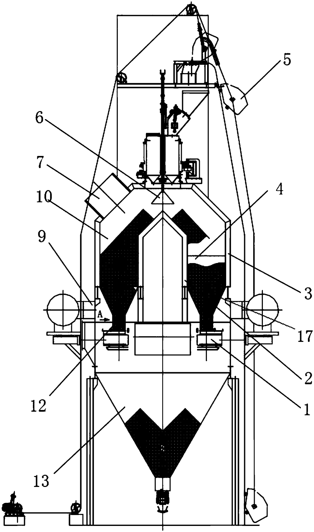
[0022] Such as Figures 1 to 3 As shown, a compartment cooling device for sinter and pellets of the present invention includes a feeding system, a feeding valve group, a vertical furnace body, a discharge valve, a secondary cooling chamber 13 and a ventilation pipeline.

[0023] The vertical furnace body includes a furnace shell 3, an inner sleeve 2 is arranged at the center of the furnace shell 3, and an annular interlayer 10 is formed between the inner sleeve 2 and the furnace shell 3, and the annular interlayer 10 is circular or polygonal.

[0024] A feeding valve group is arranged on the top of the annular interlayer 10, and the feeding valve group is connected to the feeding system. The feeding valve group includes a material inlet sealing bell valve 6 , and the feeding system includes a feeding trolley 5 . The upper part of the annular interlayer 10 is provided...


PUM


Abstract

The invention discloses a chambered cooling device for sintered ore and pellet ore. The chambered cooling device comprises a vertical furnace body, wherein the vertical furnace body comprises a furnace shell; an inner sleeve is arranged at the center of the furnace shell; an annular interlayer is formed between the inner sleeve and the furnace shell; a feeding valve group is arranged at the top of the annular interlayer; an air outlet is formed in the upper part of the annular interlayer; a plurality of partition walls are arranged at the lower part of the annular interlayer at intervals along the annular center; the lower part of the annular interlayer is divided into a plurality of material cooling chambers through the partition walls; funnel sections are arranged at the bottoms of the material cooling chambers; louver type air inlets are formed in the side surfaces of the funnel sections; air inlets are formed in the positions, corresponding to louver boards, of the furnace shell; the lower ends of the funnel sections are connected with material lateral discharge pipes; the material lateral discharge pipes are provided with lateral discharge holes; the lateral discharge holes are provided with drawer-type blow-off valves; a secondary cooling chamber is arranged below the drawer-type blow-off valves; and a blow-off valve is arranged at the bottom of the secondary cooling chamber. According to the chambered cooling device, materials can be subjected to chambered cooling and multi-point lateral pushing, discharge is achieved at the bottoms of the chambers through adopting the drawer-type blow-off valves, and the forced discharge is achieved.

Description

technical field [0001] The invention relates to the field of blast furnace smelting, in particular to a cooling device for sinter and pellets in ironworks. Background technique [0002] The working principle of the sinter pellet cooling device is: after the low-temperature gas enters the cooling device, it exchanges heat with the high-temperature sinter and pellet, and the heat of the material is taken away by the gas, thereby cooling the sinter hot ore and the pellet hot ore, and realizing waste heat Recycle. High-temperature sinter and pellets are cooled and then used as raw materials for blast furnace production [0003] The vertical (vertical) cooling device (kiln) disclosed in the existing invention patent "a vertical cooling kiln" (publication number CN 104451140 A) and utility model patent "a vertical cooling kiln" (publication number CN 203451587 U) ) has the following disadvantages: due to the different sizes of the materials, the wind resistance to the airflow is...

Claims


Application Information

Patent Timeline
Patent Type & Authority Patents(China)
IPC IPC(8): C22B1/26
CPCC22B1/26
Inventor 顾军张旭张威高有良李瑞丽
Owner MOUNTOP GRP CO LTD
Why Eureka
Try Eureka