Composite shear wall and steel truss composite beam connection energy dissipation node and its preparation method

A combined shear wall and steel truss technology, applied in the direction of truss beams, truss structures, walls, etc., can solve the problem that the bending moment and shear force of the connecting beam are difficult to effectively transmit the shear wall, and the welding area is prone to bending and tearing , increase the difficulty of construction operations, etc., to solve the problem of reliable connection, easy to guarantee the construction quality, and realize the effect of convenient construction

Active Publication Date: 2019-04-30
HEFEI UNIV OF TECH
View PDF8 Cites 0 Cited by
  • Summary
  • Abstract
  • Description
  • Claims
  • Application Information

AI Technical Summary

Problems solved by technology

Since the composite shear wall of the outsourcing steel plate is thinner than the reinforced concrete shear wall, the construction work space when the coupling beam is inserted is small, and the coupling beam of the anchorage section is generally welded with shear connectors or embedded parts, etc., which is larger The construction work is difficult and the construction speed is slow; the thickness of the outer steel plate of the outer steel plate composite shear wall is generally about 4mm, and the steel plate is thin. When the connecting beam is directly welded on the thin steel plate, it is easy to burn through during welding, and the welding deformation is difficult to control. When the area is stressed, it is easy to bend and tear, and the bending moment and shear force on the coupling beam are difficult to effectively transfer to the shear wall

Method used


Image

  • Composite shear wall and steel truss composite beam connection energy dissipation node and its preparation method
  • Composite shear wall and steel truss composite beam connection energy dissipation node and its preparation method
  • Composite shear wall and steel truss composite beam connection energy dissipation node and its preparation method

Examples


Embodiment Construction

[0047] The following will clearly and completely describe the technical solutions in the embodiments of the present invention with reference to the accompanying drawings in the embodiments of the present invention. Obviously, the described embodiments are only some, not all, embodiments of the present invention.

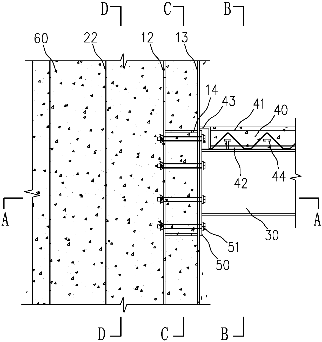
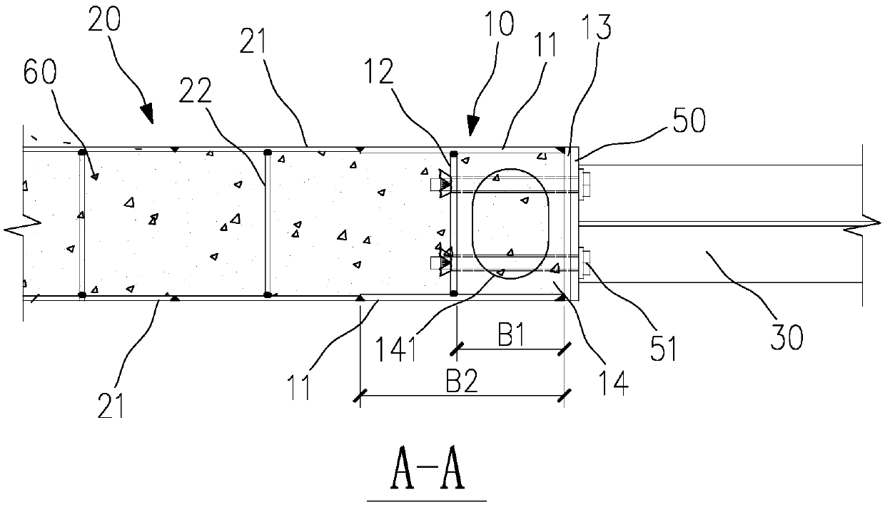
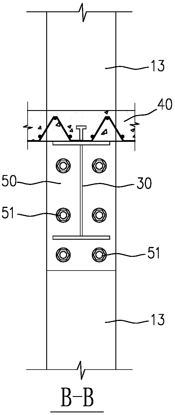
[0048] Such as Figure 1~5 As shown, a composite shear wall is connected to an energy-dissipating node with a steel truss composite beam, the composite shear wall is a steel cavity structure unit filled with concrete 60 inside, and the end of the steel cavity structure unit is provided with The edge reinforced column 10 is conveniently connected with the steel truss composite beam, and the steel truss composite beam is connected with the edge reinforced column 10 through the energy dissipation metal plate 50 and the metal connector 51 to form a hybrid connection energy dissipation node.

[0049] Such as figure 1 As shown, the steel cavity structure unit includes a s...


PUM

PropertyMeasurementUnit
thicknessaaaaaaaaaa

Abstract

The invention belongs to the technical field of building structures, and particularly relates to a composite shear wall and steel bar truss composite beam connected energy-dissipating node and a manufacturing method thereof. A composite shear wall in the connected energy-dissipating node is a steel cavity structure unit filled with concrete. An edge reinforcing column connected with a steel bar truss composite beam is arranged at the end part of the steel cavity structure unit. The steel bar truss composite beam is connected with the edge reinforcing column through an energy-dissipating metal plate and metal connecting pieces to form the hybrid connected energy-dissipating node. The composite shear wall is connected with the steel bar truss composite beam by adopting the assembly type metal connecting pieces and the energy-dissipating metal plate, field welding is not required, connection is safe and reliable, the assembly degree is high, the construction quality is easy to ensure, the construction speed is high, and the comprehensive cost-performance ratio is high. A shearing force and a bending moment in a node region can be effectively transmitted under an earthquake action, the node region and the bottom of the composite shear wall can form a plastic hinge with high ductility and high energy-dissipating capacity.

Description

technical field [0001] The invention belongs to the technical field of building structures, and in particular relates to an energy-dissipating node connected with a composite shear wall and a reinforced truss composite beam and a preparation method thereof. Background technique [0002] With the development of social economy, the increase of building height and the improvement of building function requirements, the requirements for the performance of shear walls and coupling beams also increase. In order to improve the ductility of traditional reinforced concrete shear wall structures, reduce earthquake action, speed up construction and reduce engineering costs, scholars at home and abroad have conducted a large number of experiments and theoretical studies on composite shear walls. The test results show that composite shear walls have Reinforced concrete shear walls have the advantages of high bearing capacity and high rigidity, as well as good plasticity and toughness, qui...

Claims


Application Information

Patent Timeline
Patent Type & Authority Patents(China)
IPC IPC(8): E04B1/38E04B2/56E04C3/04E04B5/02
CPCE04B1/38E04B2/56E04B5/02E04C3/04
Inventor 王静峰李贝贝王贾鑫潘学蓓
Owner HEFEI UNIV OF TECH
Why Eureka
Try Eureka