
Two-stage pushing and pressing rivet

A technology of rivets and nail inner sleeves, applied in rivets and other directions, can solve problems such as restricting the application of push-type rivets

Active Publication Date: 2016-11-16
AEROSPACE PRECISION PROD INC LTD
View PDF6 Cites 2 Cited by
  • Summary
  • Abstract
  • Description
  • Claims
  • Application Information

AI Technical Summary

Problems solved by technology

However, in some cases, the minimum expansion diameter of the blind end of the rivet after riveting is required. In many cases, the expansion diameter of the blind end of the push rivet is not sufficient, which limits the application of the push rivet

Method used


Image

  • Two-stage pushing and pressing rivet
  • Two-stage pushing and pressing rivet
  • Two-stage pushing and pressing rivet

Examples


Embodiment Construction

[0039] The invention will be further described below in conjunction with the accompanying drawings.

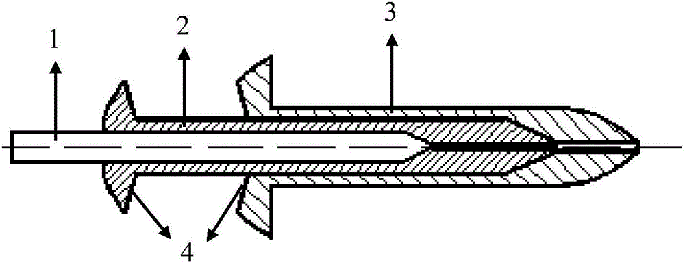
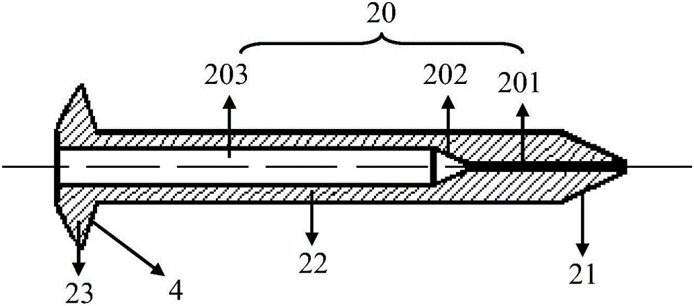
[0040] An embodiment of the inventive structure of the present invention is as Figure 1-10 As shown, it includes a core rod 1, a nail inner sleeve 2 and a nail outer sleeve 3 that are coaxially set from the inside to the outside; the core rod 1 is provided with a first tapered section 11 and a rod section 12; the nail inner sleeve 2 is provided with There is a second tapering section 21 and an inner sleeve rod section 22, and an inner sleeve through hole 20 is also provided along the shaft in the inner sleeve 2 of the nail, and the inner sleeve through hole 20 starts from the end where the second tapering section 21 is located. In turn, it includes the inner sleeve thin hole section 201, the inner sleeve tapered hole section 202 matched with the first tapered section 11 of the core rod 1, and the nail inner sleeve 2 with the rod section 12 of the core rod 1. The partly match...


PUM


Abstract

The invention provides a rivet which comprises a core rod, a rivet inner sleeve and a river outer sleeve which are coaxially sleeved in sequence from inside to outside. The core rod is provided with a first gradually-thin section and a rod section. The river inner sleeve is provided with a second gradually-thin section and an inner sleeve rod section and further provided with an inner sleeve through hole along the axis. The inner sleeve through hole sequentially comprises an inner sleeve thin hoe section, an inner sleeve gradually-thin hole section matched with the first gradually-thin section of the core rod, and an inner sleeve straight hole section matched with the portion, in the rivet inner sleeve, of the rod section of the core rod. The rivet outer sleeve is provided with an outer sleeve head and an outer sleeve rod section and further provided with an outer sleeve through hole along the axis. The outer sleeve through hole sequentially comprises an outer sleeve thin hole section, an outer sleeve gradually-thin section matched with the second gradually-thin section of the rivet inner sleeve, and an outer sleeve straight hole section matched with the portion, in the rivet outer sleeve, of the inner sleeve rod section of the rivet inner sleeve. Resources can be saved, and an enough expansion diameter can be obtained at the installation blind end.

Description

technical field [0001] The invention belongs to the technical field of fastener design and processing, and in particular relates to a rivet that can be fastened by two-stage pushing. Background technique [0002] The structure of high-end equipment such as aerospace is generally designed to be relatively compact. The connection and installation space of these compactly designed structural parts is relatively narrow. Ordinary bolts and nuts are not suitable for installation in these occasions because they need to be installed on both sides. Require. Therefore, in these narrow spaces, fasteners installed on one side are generally used, such as blind rivets and push rivets. After the blind rivet is installed, the broken mandrel will be thrown away, resulting in a waste of metal resources. The installation of push-type rivets will not cause waste of metal resources by throwing away the mandrel. However, in some cases, the minimum expansion diameter of the blind end of the riv...

Claims


Application Information

Patent Timeline
Patent Type & Authority Applications(China)
IPC IPC(8): F16B19/08
CPCF16B19/08
Inventor 郭双双郗建豪齐跃马换梅高云胡隆伟徐国琦
Owner AEROSPACE PRECISION PROD INC LTD
Learn More