
Cooling system of LED (Light Emitting Diode) lamp

A technology of LED lamps and heat dissipation systems, which is applied in cooling/heating devices of lighting devices, lighting and heating equipment, safety devices of lighting devices, etc., to achieve the effects of increasing heat dissipation area, improving lighting effect and quality, and reducing volume

Inactive Publication Date: 2016-11-16
麦健文
View PDF4 Cites 10 Cited by
  • Summary
  • Abstract
  • Description
  • Claims
  • Application Information

AI Technical Summary

Problems solved by technology

[0004] The object of the present invention is, in order to solve the above-mentioned technical problems existing in the heat dissipation of existing LED lamps, to provide a heat dissipation system for LEDs with good heat dissipation function

Method used


Image

  • Cooling system of LED (Light Emitting Diode) lamp
  • Cooling system of LED (Light Emitting Diode) lamp
  • Cooling system of LED (Light Emitting Diode) lamp

Examples


Embodiment 1

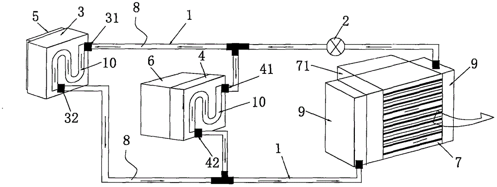
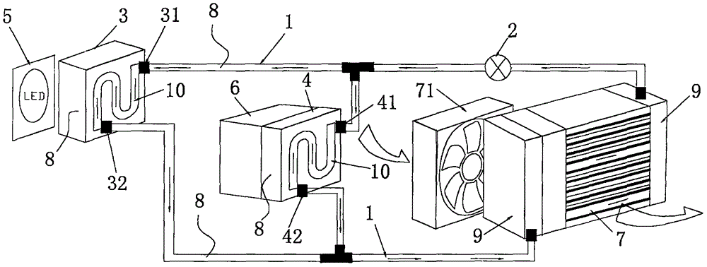
[0029] Embodiment 1: as Figure 1 to Figure 4 The heat dissipation system for an LED lamp shown includes a circulation pipe 1 and a pump 2, and also includes an LED heat dissipation module 3 and a power supply heat dissipation module 4. The LED heat dissipation module 3 is a fluid heat dissipation device for the LED lamp 5. The power cooling module 4 is a fluid cooling device for the LED lamp power module 6; the circulation pipe 1 is connected to the LED cooling module 3 and the power cooling module 4; the specific connection method is as follows figure 1 with figure 2 As shown: the LED cooling module 3, the power cooling module 4 and the circulation pipe 1 are connected in parallel; the pump 2 is installed on the circulation pipe 1, so that the fluid in the circulation pipe 1 passes through the LED heat dissipation module 3 and the power supply. The heat dissipation module 4 forms a circular flow, thereby realizing the heat dissipation and cooling functions of the LED lamp ...

Embodiment 2

[0036] Embodiment 2: The technical feature of this embodiment is that no heat pipe 10 is needed in the LED cooling module 3 (sealed box 1) and the power cooling module 4 of the power module 6 (sealed box 2). All the other are the same as the above embodiment.

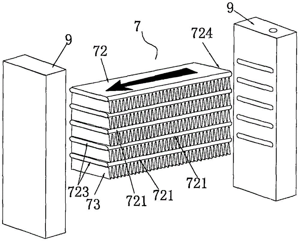
[0037] When the present invention is applied, the LED cooling module 3 (sealed box one), the power supply cooling module 4 (sealed box two) and the water collection tank 9 are filled with fluid 8, and the fluid 8 includes silicone oil, water, etc. Coolant with thermal conductivity. When the LED light is turned on, the water pump 2 on the circulation pipe 1 is started at the same time, so that the fluid 8 flows between the LED heat dissipation module 3 (sealed box 1) of the LED light 5 and the power heat dissipation module 4 of the power module 6 (sealed box 2) Circulating flow between the water collection tank 9 of the radiator 7. During the fluid circulation process, the heat generated by the LED lamp 5 is transferre...

Embodiment 3

[0038] Embodiment 3: as Figure 5 The heat dissipation system for LED lamps shown in this embodiment has the technical characteristics that: the LED heat dissipation module 3 , the power supply heat dissipation module 4 and the circulation pipe 1 are connected in series. All the other are the same as the above embodiment.


PUM


Abstract

The invention relates to a heat dissipation system for an LED lamp, comprising a circulation pipe (1) and a pump (2), and also includes an LED heat dissipation module (3) and a power supply heat dissipation module (4), the LED heat dissipation module (3) ) is a fluid cooling device for the LED lamp (5), and the power cooling module (4) is a fluid cooling device for the LED lamp power module (6); the circulation pipe (1) is connected to the LED cooling module (3) and the power supply A heat dissipation module (4); the pump (2) is installed on the circulation pipe (1), so that the fluid in the circulation pipe (1) passes through the LED heat dissipation module (3) and the power supply heat dissipation module (4) to form a circulating type flow, thereby simultaneously realizing the heat dissipation and cooling functions of the LED lamp (5) and the power module (6). The invention not only effectively guarantees the heat dissipation effect of the whole LED lamp equipment, improves the lighting effect and quality of the LED lamp, but also prevents the power module from being damaged by heat, so that the service life can be effectively prolonged.

Description

technical field [0001] The invention relates to a heat dissipation device for an LED lamp. Background technique [0002] As we all know, LED has high luminous efficiency, long life and low power consumption, so it is widely popularized and applied. However, due to the high temperature of LED lamps during application, the luminous intensity will be reduced, thereby affecting luminous efficiency and lighting quality, and seriously affecting Its service life, especially when applied to high-power LED lamps, is particularly prominent, so the technical problem of excessive temperature has become a major obstacle to the popularization and promotion of LED lamps. [0003] The heat dissipation of existing LED lights is mainly divided into two types: air-cooled heat dissipation structure and liquid-cooled heat dissipation structure. Due to the slow cooling speed, air-cooled heat dissipation is difficult to be used in large-function LED lights. Although the liquid-cooled heat dissipat...

Claims


Application Information

Patent Timeline
Patent Type & Authority Applications(China)
IPC IPC(8): F21K9/20F21V29/503F21V29/508F21V29/67F21V29/58F21V29/74F21V25/00F21Y115/10
CPCF21V29/503F21V25/00F21V29/508F21V29/58F21V29/67F21V29/74
Inventor 麦健文
Owner 麦健文
Learn More