A workpiece drying device

A technology for drying devices and workpieces, which is applied in drying, drying machines, drying gas arrangement, etc., and can solve the problems of increasing loading and unloading of workpieces, not having too many workpieces, and reducing production efficiency.

Inactive Publication Date: 2018-10-19
SHANDONG UNIV
View PDF4 Cites 0 Cited by
  • Summary
  • Abstract
  • Description
  • Claims
  • Application Information

AI Technical Summary

Problems solved by technology

[0002] Workpieces often need to be cleaned after processing. Since the cleaned workpieces cannot be dried quickly, natural drying is often carried out in the prior art, which affects production efficiency. In the prior art, there are also drying machines for drying. The drying machine consists of a drying bucket driven by a motor. During the rotation of the drying bucket, the liquid attached to the surface of the workpiece will be thrown out to achieve the purpose of drying, but this drying machine is only suitable for workpieces with a small quality, and There should not be too many workpieces to be dried at the same time. For workpieces with large mass, the dryer cannot be dried, and when the dryer is used for drying, the workpieces need to be put into the drying barrel, which increases the weight of the workpieces. A series of processes such as loading and unloading reduces production efficiency

Method used


Image

  • A workpiece drying device
  • A workpiece drying device
  • A workpiece drying device

Examples


Embodiment Construction

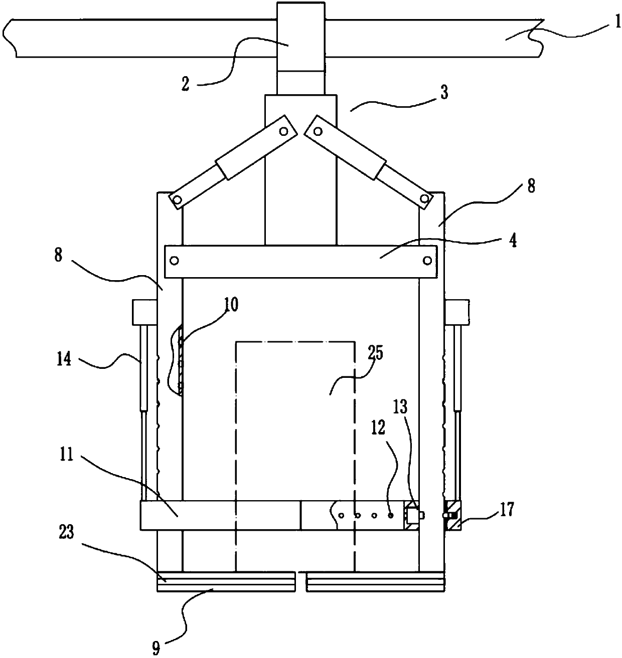
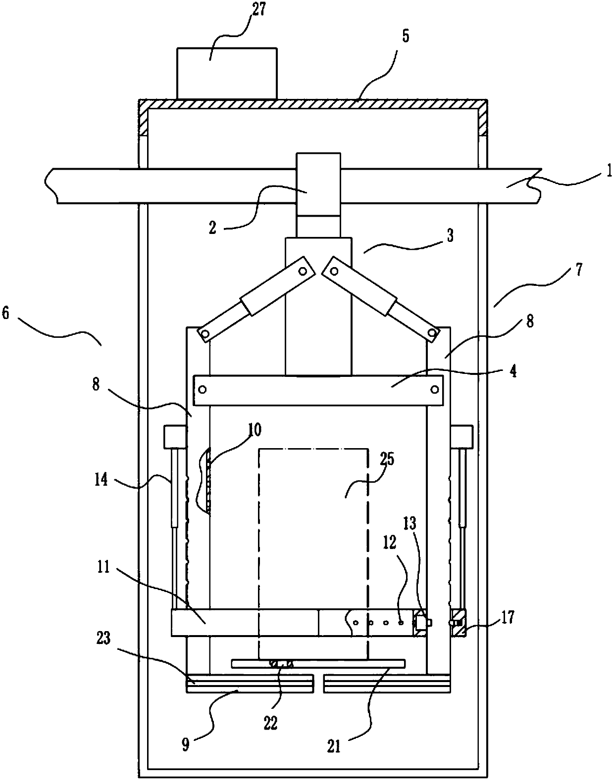
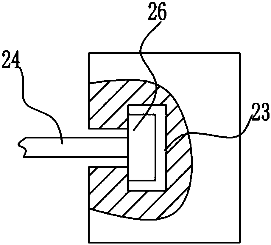
[0015] Such as figure 1 , figure 2 , image 3 with Figure 4 As shown, a workpiece drying device includes a frame, the upper part of the frame is provided with a guide rail 1, a sliding seat 2 is slidably installed on the guide rail 1, and a vertical bar is provided on the lower surface of the sliding seat 2 3. A mounting base 4 is installed on the lower end of the vertical rod 3, and a drying shell 5 is also installed on the frame, and an exhaust fan 27 is arranged inside the drying shell 5, and the drying shell 5 There is a feed port 6 and a discharge port 7, the guide rail 1 enters the drying shell 5 from the feed port 6 and extends out of the drying shell from the discharge port 7, so The outer periphery of the mounting seat 4 is hinged with a plurality of swing rods 8, and the swing rods 8 are connected with a swing drive device that drives the swing rods 8 to deflect so that the lower ends of each of the swing rods 8 approach or separate from each other. The lower e...


PUM


Abstract

The invention relates to a workpiece drying device. The workpiece drying device comprises a machine frame, a guide rail is arranged on the upper portion of the machine frame, and a sliding base is installed on the guide rail in a sliding mode. A vertical rod is arranged on the lower surface of the sliding base, and a mounting base is installed at the lower end of the vertical rod. A drying shell is further installed on the machine frame. An exhaust fan is arranged inside the drying shell. The drying shell is provided with a feed inlet and a discharge outlet. The guide rail enters the drying shell from the feed inlet and extends out of the drying shell from the discharge outlet. A plurality of swing rods are hinged to the periphery of the mounting base. The swing rods are connected with a swing driving device which drives the swing rods to deflect so that the lower ends of the swing rods can get close to or be separated from one another. The swing driving device drives the swing rods to get close to one another, a workpiece is supported by supporting rods and grabbed by the swing rods, a gas spraying hole sprays heated gas to the workpiece, the sliding base moves along the guide rail in the process, and therefore the mounting base is made to drive the swing rods to move, the workpiece is driven to move, drying of the workpiece is achieved in the conveying process, and production efficiency is greatly improved.

Description

technical field [0001] The invention relates to a drying device. Background technique [0002] Workpieces often need to be cleaned after processing. Since the cleaned workpieces cannot be dried quickly, natural drying is often carried out in the prior art, which affects production efficiency. In the prior art, there are also drying machines for drying. The drying machine consists of a drying bucket driven by a motor. During the rotation of the drying bucket, the liquid attached to the surface of the workpiece will be thrown out to achieve the purpose of drying, but this drying machine is only suitable for workpieces with a small quality, and There should not be too many workpieces to be dried at the same time. For workpieces with large mass, the dryer cannot be dried, and when the dryer is used for drying, the workpieces need to be put into the drying barrel, which increases the weight of the workpieces. A series of processes such as loading and unloading reduces production...

Claims


Application Information

Patent Timeline
Patent Type & Authority Patents(China)
IPC IPC(8): F26B15/00F26B21/00F26B25/02F26B25/04F26B25/00
CPCF26B15/00F26B21/00F26B25/00F26B25/02F26B25/04
Inventor 于金伟张美荣王春晓
Owner SHANDONG UNIV
Why Eureka
Try Eureka