
A test device and verification method for verifying the function of a lubricating oil pump after a lubricating oil interruption

A technology of test device and test method, applied in jet engine test, gas turbine engine test, etc., can solve problems such as the danger of the whole engine and the lack of a clear test method for the lubricating oil pump, so as to reduce the risk of the lubricating oil interruption test and save the cost , low risk effect

Active Publication Date: 2018-12-11
AECC SHENYANG ENGINE RES INST
View PDF6 Cites 2 Cited by
  • Summary
  • Abstract
  • Description
  • Claims
  • Application Information

AI Technical Summary

Problems solved by technology

After 30 seconds, the lubricating oil pump should be able to restore the engine oil supply immediately, otherwise it will cause danger to the whole engine
[0003] At present, domestic lubricating oil interruption tests are all carried out on the whole machine of the aero-engine, and there is no separate tester designed to verify whether the newly developed lubricating oil pump can restore the normal oil supply after sucking air, which has a relatively large risk. The lubricating oil pump cannot restore the oil supply after the engine oil is cut off for 30 seconds, which will cause great danger to the whole engine. However, there is no clear test method in China to verify whether the lubricating oil pump can restore the oil supply after the oil is cut off.

Method used


Image

  • A test device and verification method for verifying the function of a lubricating oil pump after a lubricating oil interruption
  • A test device and verification method for verifying the function of a lubricating oil pump after a lubricating oil interruption

Examples


Embodiment Construction

[0028] In order to make the objectives, technical solutions and advantages of the present invention clearer, the technical solutions in the embodiments of the present invention will be described in more detail below in conjunction with the drawings in the embodiments of the present invention. In the drawings, the same or similar reference numerals denote the same or similar elements or elements having the same or similar functions throughout. The described embodiments are some, but not all, embodiments of the invention. The embodiments described below by referring to the figures are exemplary and are intended to explain the present invention and should not be construed as limiting the present invention. Based on the embodiments of the present invention, all other embodiments obtained by persons of ordinary skill in the art without making creative efforts belong to the protection scope of the present invention. Embodiments of the present invention will be described in detail b...


PUM


Abstract

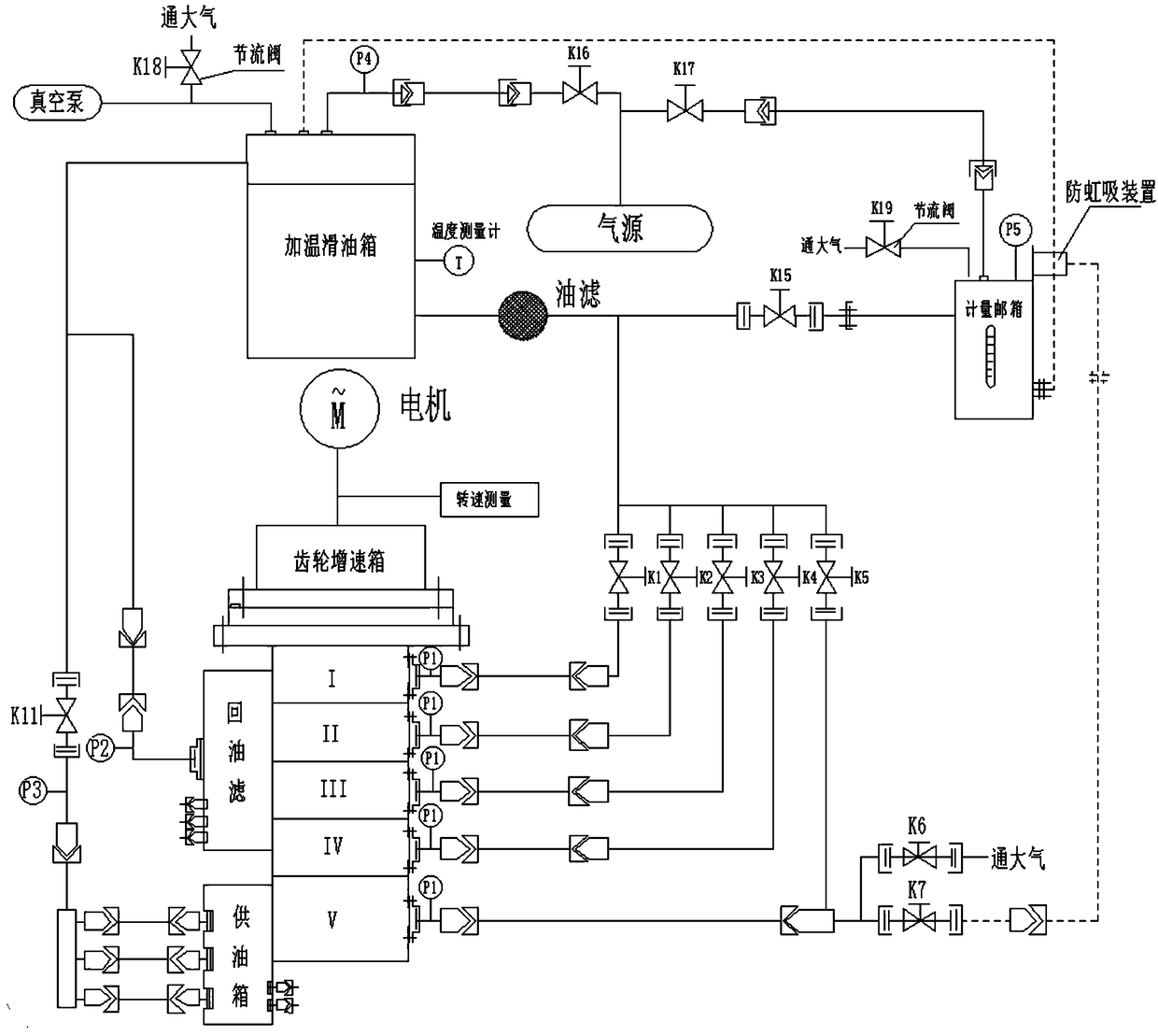
The invention relates to a test apparatus for verifying a lubricating oil pump function after a lubricating oil interruption. The test apparatus for verifying the lubricating oil pump function after the lubricating oil interruption comprises a lubricating oil pump test system, a connecting pipe and two air valves, wherein the two air valves are respectively a normally-open air valve and a normally-closed air valve and connect a heating lubricating oil tank, a metering oil tank and a lubricating oil pump group in the lubricating oil pump test system through the connecting piece, the normally-open air valve is arranged between the metering oil tank and the lubricating oil pump group, and the normally-closed air valve is also connected in parallel with the normally-open air valve for communicating with air. The invention further provides a test method for verifying a lubricating oil pump function after a lubricating oil interruption by use of the test apparatus for verifying the lubricating oil pump function after the lubricating oil interruption. The test apparatus and the verification method can effectively verify oil supply recovery performance of a lubricating oil pump after the oil interruption, reduce the risk of performing a lubricating oil interruption test on a whole-vehicle test engine, verify the capability of the lubricating oil, and also have the advantages of low risks, low cost, high convenience and practicality and the like.

Description

technical field [0001] The invention belongs to the technical field of aviation gas turbines, and in particular relates to a test device and a verification method for verifying the function of a lubricating oil pump after lubricating oil is interrupted. Background technique [0002] The aviation gas turbine engine lubricating oil system is an important part of the aviation gas turbine engine. It is mainly responsible for the lubrication of the engine's high and low pressure rotor fulcrum bearings, transmission gears and other components. At present, aero-engines must have the ability to interrupt the lubricating oil for 30s in the maximum or intermediate state, and it needs to be verified in the test run of the whole machine. This requires the lubricating oil pump to stop supplying oil to each bearing cavity of the engine during the test run, and suck air for 30 seconds to test the oil cut-off capability of the engine bearings. After 30 seconds, the lubricating oil pump sho...

Claims


Application Information

Patent Timeline
Patent Type & Authority Patents(China)
IPC IPC(8): G01M15/14
CPCG01M15/14
Inventor 刘晨昊谷俊焦自涛毛福荣苏媛媛
Owner AECC SHENYANG ENGINE RES INST
Learn More