
Electrowetting display panel and control method thereof

An electrowetting display and electrowetting display technology, applied in static indicators, optics, instruments, etc., can solve the problems of low contrast, large loss of light transmittance, and affecting the display performance of transparent display screens, so as to improve the contrast Effect

Inactive Publication Date: 2016-11-16
BOE TECH GRP CO LTD
View PDF6 Cites 9 Cited by
  • Summary
  • Abstract
  • Description
  • Claims
  • Application Information

AI Technical Summary

Problems solved by technology

[0003] However, due to the high transparency of the transparent display screen itself, the contrast ratio is low when displayed, and the color film as the basis of the color display causes a large loss of light transmittance, and one of its sub-pixels only corresponds to one of the three primary colors (RGB). Seriously affected the display performance of the transparent display

Method used


Image

  • Electrowetting display panel and control method thereof
  • Electrowetting display panel and control method thereof
  • Electrowetting display panel and control method thereof

Examples


no. 1 example

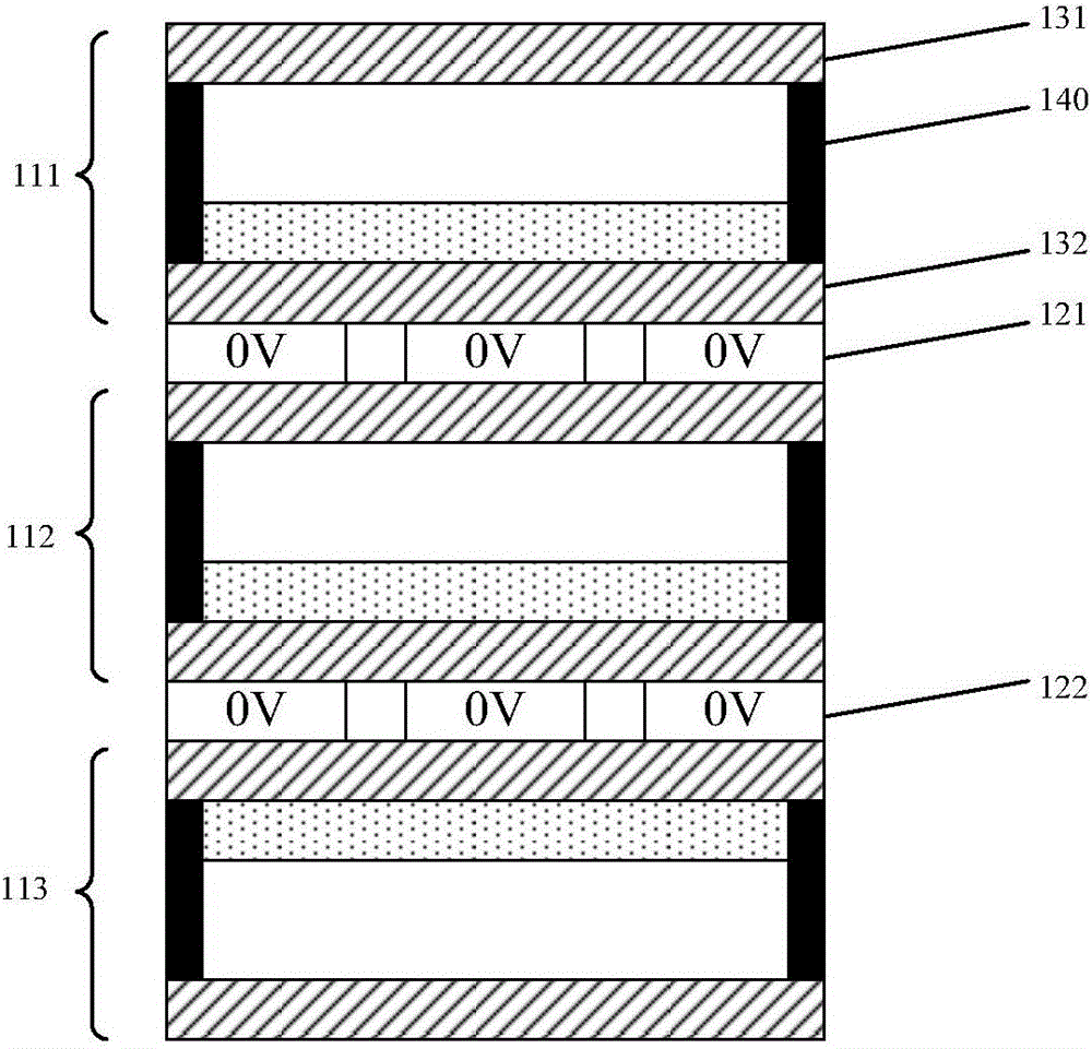
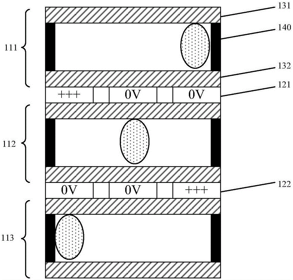
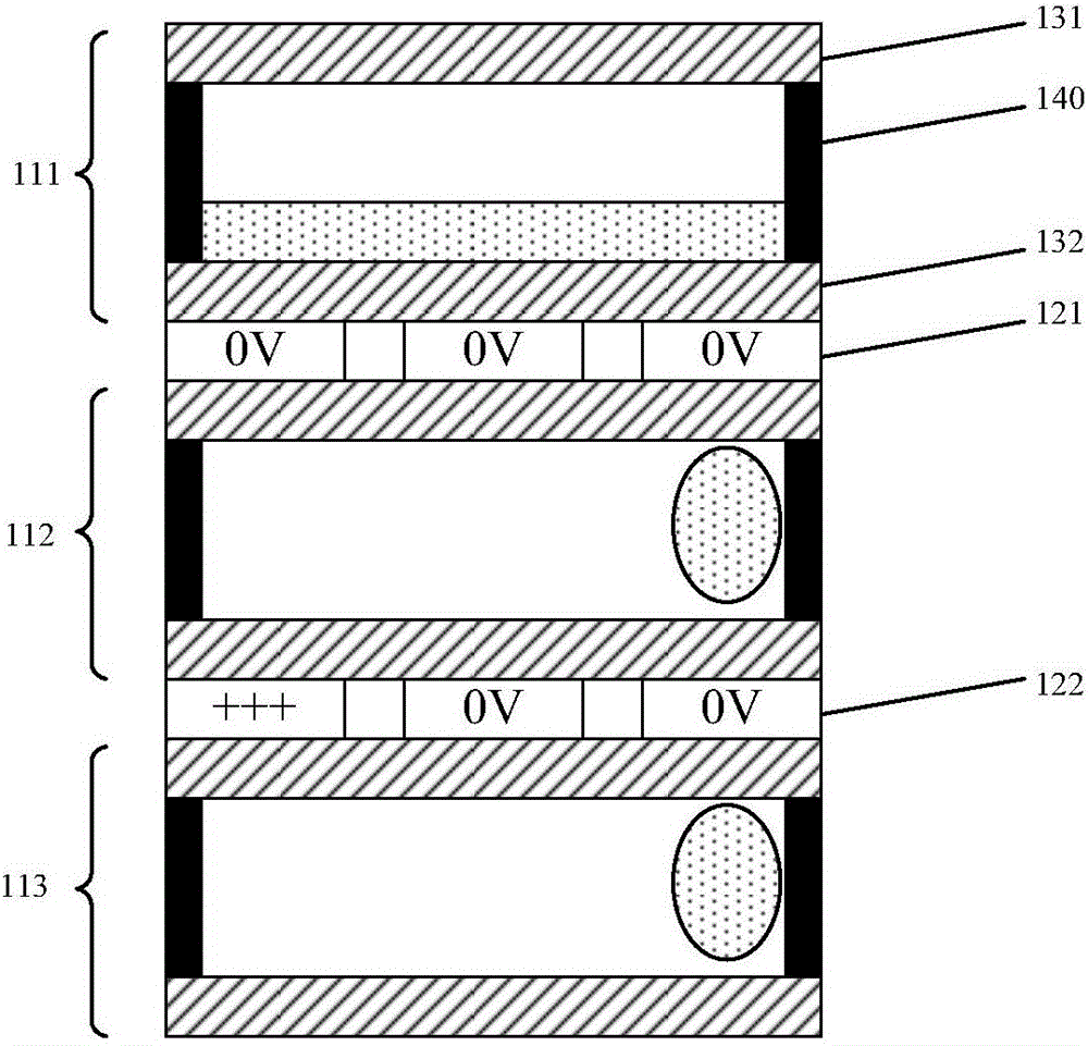
[0057] In this embodiment, the sub-pixel unit of the electrowetting display panel includes a laminated first liquid layer, a first electrode layer, a second liquid layer, a second electrode layer, and a third liquid layer, wherein each liquid layer includes a liquid , a first insulating layer, a second insulating layer, and a side wall, wherein the liquid is contained in a space surrounded by the first insulating layer, the second insulating layer, and the side wall, and the liquid includes a colored hydrophobic flow medium (i.e., non- Polar flow media, e.g., colored oily media, such as colored inks) and transparent hydrophilic flow media (i.e., polar flow media, such as water, aqueous solutions, or alcohols, such as electrolytic solutions), and The insulating layer adjacent to the electrode layer is a hydrophobic insulating layer.

[0058] In this embodiment, the electrowetting display panel can be transmissive, semi-transmissive or reflective, and can use backlight or ambien...

no. 2 example

[0086] In this embodiment, the sub-pixel unit of the electrowetting display panel includes a stacked first electrode layer, a first liquid layer, a second electrode layer, a second liquid layer, and a third electrode layer, wherein each liquid layer includes a liquid , a first insulating layer, a second insulating layer, and a side wall, wherein the liquid is contained in a space surrounded by the first insulating layer, the second insulating layer, and the side wall, and the liquid includes a colored hydrophobic flow medium (i.e., non- Polar flow media, for example, colored oily media, such as colored inks) and transparent hydrophilic flow media (i.e., polar flow media, such as water, aqueous solutions, or alcohols, such as electrolyte solutions), respectively The insulating layer adjacent to the first electrode layer and the third electrode layer is a hydrophobic insulating layer.

[0087] In this embodiment, the electrowetting display panel can be transmissive, semi-transmi...


PUM


Abstract

The invention relates to an electrowetting display panel and a control method thereof. The electrowetting display panel comprises a plurality of pixel units; and each pixel unit consists of a plurality of sub pixel units. Each sub pixel unit includes at least two liquid layers and at least one electrode layer. Each liquid layer and each electrode layer are laminated alternately. Each liquid layer consists of liquid, a first insulation layer, a second insulation layer, and a side wall; the liquid is accommodated into the space encircled by the first insulation layer, the second insulation layer, and the side wall and includes a hydrophobic flow medium with a color and a transparent hydrophilic flow medium. And the insulation layer adjacent to the electrode layer in each liquid layer is a hydrophobic insulation layer.

Description

technical field [0001] The invention relates to electrowetting display technology, in particular to an electrowetting display panel and a control method thereof. Background technique [0002] With the continuous development of display technology, transparent display screens have become the research focus of various display panel manufacturers. Compared with traditional liquid crystal display screens, transparent display screens can bring users unprecedented visual experience and brand-new experience. Since the transparent screen itself has the characteristics of screen and transparency, it can be applied to many occasions, that is, it can be used as a screen and can replace transparent flat glass. The user can see objects or images on the opposite surface through the screen. [0003] However, due to the high transparency of the transparent display screen itself, the contrast ratio is low when displayed, and the color film as the basis of the color display causes a large los...

Claims


Application Information

Patent Timeline
Patent Type & Authority Applications(China)
IPC IPC(8): G02B26/00G09G3/34
CPCG09G3/348G02B26/005G09G3/2003G09G2300/0404G09G2300/0426
Inventor 肖丽陈小川杨盛际刘冬妮王磊付杰卢鹏程岳晗
Owner BOE TECH GRP CO LTD
Learn More