Novel connector press button type two-stage unlocking mechanism
What is Al technical title?
Al technical title is built by PatSnap Al team. It summarizes the technical point description of the patent document.
A technology of unlocking mechanism and connector, which is applied to vehicle connectors, connections, parts of connecting devices, etc., can solve the problems of complex structure, high maintenance cost, and difficult use of step-by-step locking devices.
Active Publication Date: 2016-11-16
SHENZHEN BUSBAR SCI TECH DEV
View PDF4 Cites 3 Cited by
Summary
Abstract
Description
Claims
Application Information
AI Technical Summary
This helps you quickly interpret patents by identifying the three key elements:
Problems solved by technology
Method used
Benefits of technology
Problems solved by technology
[0002] At present, with the huge demand for new energy vehicles in the world, the field of rechargeable electric vehicles is developing rapidly, but charging safety is one of the problems that limit the development of rechargeable electric vehicles
At present, one of the commonly used charging protection measures is to install protective components on the connector port of electric vehicles, most of which are openable cover-shaped components, but this type of product still has a large hidden danger of power consumption, especially in the case of high voltage , and the openable cover has the disadvantage of being easy to be opened or opened by mistake
[0003] The step-by-step locking device developed on the basis of the open-type cover-shaped parts has better reliability and safety, but the existing step-by-step locking device has a complicated structure, is difficult to use, and has relatively high maintenance costs. high
Method used
Image
Click on the blue label to locate the original text in one second.
Reading with bidirectional positioning of images and text.
Examples
Embodiment 1
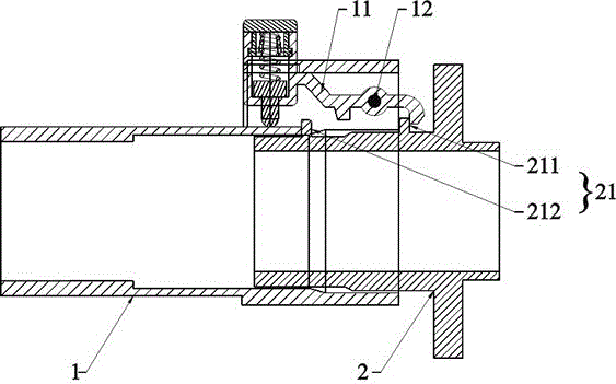
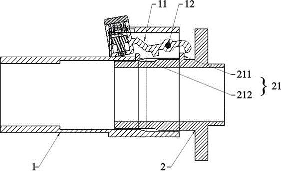
[0041] as attached figure 2 to attach Figure 8 As shown, a new connector button-type two-stage unlocking mechanism includes a plug part 1 and a socket part 2; the plug part 1 and the socket part 2 can be mated.
[0042] The plug part 1 includes a rocker assembly 11 and a fixed shaft 12 .
[0043] The socket part 2 includes a fixing position assembly 21 .
[0044] When the plug part 1 and the socket part 2 are mated, the seesaw component 11 can be fastened in the fixed position component 21 .
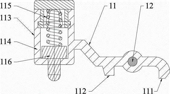
[0045] as attached figure 1 As shown, the seesaw assembly 11 is axially connected to the mating end of the plug part 1 through the fixed shaft 12, so that the seesaw assembly 11 can rotate around the fixed shaft 12;
[0046] The seesaw assembly 11 includes a fastener 111 , a locking member 112 and a pressing member 113 .
[0047] The buckle 111 and the pressing piece 113 are respectively arranged on the near mating end and the far mating end of the seesaw assembly 11 .
[0048] T...
Embodiment 2
[0059] On the basis of embodiment one, as attached figure 1 As shown, the pressing member 113 includes a button body 114, an elastic member 115 and a fulcrum 116, wherein the fulcrum 116 is in a “T” shape. The button body 114 is a hollow structure with an open bottom. Both the elastic piece 115 and the fulcrum piece 116 are arranged in the cavity of the button body 114; wherein, the lower part of the fulcrum piece 116 can pass through the opening, and abut against the plug part 1 to form a fulcrum; meanwhile, the fulcrum piece 116 is supported by the elastic piece 115 Tightly above the cavity.
[0060] When the pressing piece 113 is pressed, the elastic piece 115 is compressed, the lower part of the fulcrum piece 116 passes through the opening completely, the fastener piece 111 is tilted up, and the clip 112 is lowered; The lower part of 116 does not pass through the opening completely, the fastener 111 resets, and the clamp 112 rises.
[0061] And the elastic member 115 ca...
PUM
Abstract
The invention relates to the field of connectors and specifically relates to a novel connector press button type two-stage unlocking mechanism. When a plug head part is plugged in a plug seat part in a matched manner, a teeterboard type assembly can be tightly fastened in a fixed position assembly. The teeterboard type assembly is connected on a matching plug end of the plug head part via a fixed shaft; the teeterboard type assembly comprises a fastening member, a clamping member and a pressing member. The fastening member and the pressing member are respectively arranged on a near matching plug end and a far matching plug end of the teeterboard type assembly. The clamping member is arranged on a middle part of the teeterboard type assembly. A shaft hole of the fixed shaft is arranged between the fastening member and the clamping member. The fixed position assembly is arranged on a matching plug end of the plug seat part and comprises a fastening position and a clamping position, wherein the fastening position is arranged on a far matching plug end while the clamping position is arranged on a near matching plug end. The beneficial effects of the novel connector press button type two-stage unlocking mechanism are that the mechanism is simple in structure and is easy to manufacture and maintain, the mechanism is also simple and convenient to operate, reliability and safety of the mechanism are improved via a two-stage type unlocking mode, the mechanism can be prevented from loosening or being unlocked mistakenly, and safety of electricity utilization can be guaranteed to a maximum degree.
Description
technical field [0001] The invention relates to the field of connectors, in particular to a novel connector button-type two-stage unlocking mechanism. Background technique [0002] At present, with the huge demand for new energy vehicles in the world, the field of rechargeable electric vehicles is developing rapidly, but charging safety is one of the problems that limit the development of rechargeable electric vehicles. At present, one of the commonly used charging protection measures is to install protective components on the connector ports of electric vehicles, mostly openable cover-shaped components, but such products still have a large hidden danger of power consumption, especially in the case of high voltage , and the openable cover has the disadvantage of being easy to be opened or opened by mistake. [0003] The step-by-step locking device developed on the basis of the open-type cover-shaped parts has better reliability and safety, but the existing step-by-step lo...
Claims
Application Information
Patent Timeline
Application Date:The date an application was filed.
Publication Date:The date a patent or application was officially published.
First Publication Date:The earliest publication date of a patent with the same application number.
Issue Date:Publication date of the patent grant document.
PCT Entry Date:The Entry date of PCT National Phase.
Estimated Expiry Date:The statutory expiry date of a patent right according to the Patent Law, and it is the longest term of protection that the patent right can achieve without the termination of the patent right due to other reasons(Term extension factor has been taken into account ).
Invalid Date:Actual expiry date is based on effective date or publication date of legal transaction data of invalid patent.