Check patentability & draft patents in minutes with Patsnap Eureka AI!

Surveillance camera, home appliance control system and method thereof

A monitoring camera and home appliance control technology, which is applied in the field of home appliance control systems and monitoring cameras, can solve problems such as unfavorable installation, large camera size, and complex composition of home appliance control systems, and achieve simple composition and strong practicability

Active Publication Date: 2019-07-02
SHENZHEN XINGUODU PAYMENT TECH CO LTD
View PDF5 Cites 0 Cited by
  • Summary
  • Abstract
  • Description
  • Claims
  • Application Information

AI Technical Summary

Problems solved by technology

[0002] At present, there are many types of monitoring cameras on the market, and their functions are very powerful. In addition to the conventional real-time monitoring functions, some cameras that combine real-time monitoring and infrared remote control functions have appeared on the market, but the realization of the infrared remote control function is complicated, and the structure of the camera is complicated. And the camera is large in size, which leads to high manufacturing cost of the camera, which is not conducive to widespread promotion and use. The large size of the surveillance camera is also not conducive to actual installation, which does not conform to the trend of modern industrial intelligence and miniaturization; the composition of the existing home appliance control system is complex , the control method of home appliances is complex and single, which cannot meet the needs of users

Method used


Image

  • Surveillance camera, home appliance control system and method thereof
  • Surveillance camera, home appliance control system and method thereof
  • Surveillance camera, home appliance control system and method thereof

Examples


Embodiment Construction

[0044] It should be noted that, in the case of no conflict, the embodiments in the present application and the features in the embodiments can be combined with each other.

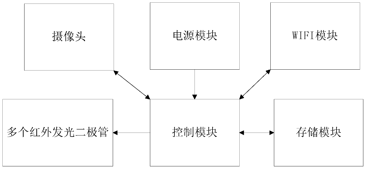
[0045] A surveillance camera, reference figure 1 , figure 1 It is a structural block diagram of a monitoring camera in the present invention, and the monitoring camera includes a control module as an information processing center and a control center of the monitoring camera; a plurality of infrared light-emitting diodes whose input ends are respectively connected to the output ends of the control module are used for The infrared modulation signal sent by the control module is received; the camera, the WIFI module and the storage module are respectively connected to the control module; the output terminal is connected to the power supply module of the input terminal of the control module.

[0046] A monitoring camera in the present invention can send infrared modulation signals to multiple infrared light-...


PUM


Abstract

The invention discloses a monitoring camera, comprising a control module, multiple infrared light emitting diodes, a camera, a WIFI module, a storage module and a power supply module. The invention also discloses a household electrical appliance control system, comprising the monitoring camera, a mobile terminal and a cloud server. The invention also discloses a household electrical appliance control method. According to the monitoring camera provided by the invention, real-time monitoring can be realized, and real-time household electrical appliance control also can be realized. According to the household electrical appliance control system provided by the invention, the composition is simple, household electrical appliance control of various different modes can be realized, and the practicability is high. According to the household electrical appliance control method applied to the household electrical appliance control system, a household electrical appliance system can be automatically controlled through the local monitoring camera. The invention also provides a method for controlling the household electrical appliance system remotely by employing the mobile terminal. Different demands of a user can be satisfied through the control of different modes. The monitoring camera, and the household electrical appliance control system and method can be widely applied to the field of household electrical appliance control.

Description

technical field [0001] The invention relates to the field of home appliance control, in particular to a monitoring camera, a home appliance control system and a method thereof. Background technique [0002] At present, there are many types of monitoring cameras on the market, and their functions are very powerful. In addition to the conventional real-time monitoring functions, some cameras that combine real-time monitoring and infrared remote control functions have appeared on the market, but the realization of the infrared remote control function is complicated, and the structure of the camera is complicated. And the camera is large in size, which leads to high manufacturing cost of the camera, which is not conducive to widespread promotion and use. The large size of the surveillance camera is also not conducive to actual installation, which does not conform to the trend of modern industrial intelligence and miniaturization; the composition of the existing home appliance con...

Claims


Application Information

Patent Timeline
Patent Type & Authority Patents(China)
IPC IPC(8): H04N7/18H04L12/28
CPCH04L12/2803H04L12/2816H04N7/18
Inventor 刘祥洪
Owner SHENZHEN XINGUODU PAYMENT TECH CO LTD
Features
  • R&D
  • Intellectual Property
  • Life Sciences
  • Materials
  • Tech Scout
  • Unparalleled Data Quality
  • Higher Quality Content
  • 60% Fewer Hallucinations
Learn More