Connection arrangement of a piston rod

A technology for operating devices and working cylinders, applied in mechanical equipment, non-mechanical drive clutches, fluid pressure actuating devices, etc., can solve problems such as the loss of piston rods and the loosening of anti-loss devices from stop rings.

Active Publication Date: 2016-11-16
SCHAEFFLER TECH AG & CO KG
View PDF5 Cites 4 Cited by
  • Summary
  • Abstract
  • Description
  • Claims
  • Application Information

AI Technical Summary

Problems solved by technology

However, due to the force exerted by the preloaded spring inside the master cylinder on the clamping connection via the piston rod, there is the danger that the locking element of the clamping connection separates from the stop ring
I

Method used


Image

  • Connection arrangement of a piston rod
  • Connection arrangement of a piston rod
  • Connection arrangement of a piston rod

Examples


Embodiment Construction

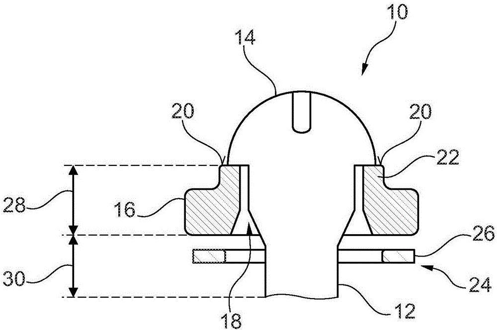
[0024] figure 1 The actuating device 10 of a working cylinder, which is designed as a master cylinder of a hydraulic coupling device of a motor vehicle, is shown in a sectional view. The actuating device 10 is thus a component of that cylinder. The working cylinder is integrated with its components: the cylinder housing, the piston mounted displaceably in the cylinder housing, and the preload spring which moves the piston into the basic position, but not shown.

[0025] The actuating device 10 has a piston rod 12 which itself has a piston rod foot 14 at the end. exist figure 1 The central piston rod 14 is in the delivery position, which corresponds to the working position of the working cylinder for a right-hand drive motor vehicle or for a left-hand drive motor vehicle. The operating device 10 is mechanically attached via a piston rod foot 14 to a piston of a working cylinder (not shown). In the case of working cylinders designed as master cylinders, the piston rod is the...


PUM


Abstract

The invention relates to an actuating device for mechanical connection to a piston of a working cylinder, comprising a piston rod (12), which has a piston-rod base (14) at one end, a stop ring (16) for the piston-rod base (14), which stop ring accommodates the piston rod (12) in the interior of the stop ring with play, wherein the piston-rod base can pass through the stop ring (16) in at least one angular position of the piston rod (12) in relation to the stop ring, and a retaining device (24) to prevent such passing through, which retaining device has a main body (28) and a clip device. The clip device has at least one clip element (36, 38) comprising a spring arm (40, 42), which is fastened to the main body (26) and reaches through the interior of the stop ring (16) parallel to the piston rod, and comprising a latching projection (44, 46), which is arranged on the spring arm, wherein the remaining play S of the assembly of the piston rod and the at least one spring arm in the interior of the stop ring, with the piston-rod base lying against the stop ring or the clip element and being in the angular position permitting the passing through, is less than the rearward-engagement length L of the at least one latching projection.

Description

technical field [0001] The invention relates to an operating device for mechanical attachment to a piston of a working cylinder, in particular a master cylinder, of a hydraulic brake or clutch device. The operating device comprises a piston rod with a piston rod foot on the end; a stop ring for the piston rod foot, which receives the piston rod with play in the interior of the stop ring, wherein the stop The ring can be penetrated by the piston rod foot in at least one angular position of the piston rod relative to the stop ring; The device enables the anti-dropping device to be fastened releasably on the stop ring. The actuating device is thus a subassembly for the corresponding working cylinder. [0002] Furthermore, the invention relates to a corresponding working cylinder of a hydraulic brake or clutch device, said working cylinder having a cylinder housing, a piston mounted displaceably in the cylinder housing, and a corresponding working cylinder for mechanically attac...

Claims


Application Information

Patent Timeline
IPC IPC(8): F15B15/20F15B7/08F16D25/08
CPCF15B7/08F15B15/20F15B2215/30F16D25/08F15B15/1447F16D25/12F16D2025/081
Inventor T·尼森S·波普
Owner SCHAEFFLER TECH AG & CO KG
Why Eureka
Try Eureka