

Drilling and planting machine
A technology of drilling pits and reducers, which is applied in application, excavation/covering trenches, planting methods, etc., can solve the problems of high labor intensity and low efficacy, and achieve the effect of labor intensity
Inactive Publication Date: 2016-11-23
刘清海
View PDF0 Cites 3 Cited by
- Summary
- Abstract
- Description
- Claims
- Application Information
AI Technical Summary
Problems solved by technology
[0002] At present, it is well known that manpower digs a hole with a shovel and puts the saplings in. The disadvantages of this primitive and backward method of planting saplings are that it is labor-intensive and has low efficacy, and cannot keep up with the needs of modern agricultural development.
Method used
View moreImage
Smart ImageViewing Examples

Examples
Embodiment Construction
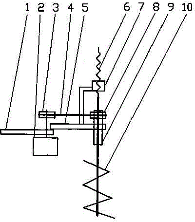
[0009] in figure 1 The reducer (2) is installed on the agricultural frame (1), the transmission wheel (3) is fastened on the reducer (2), and the transmission belt (4) and the driven wheel (8) are connected together to transmit power. . The auger lifting frame (5) is fastened to the agricultural frame (1), the screw nut (7) is fastened to the auger lifting frame (5), the screw rod (6) is set in the middle, and the inner square and outer tube (9) The auger (10) set in the middle is blocked and operated by the driven wheel (8) on the auger lifting frame (5). The upper half of the auger (10) is installed in the inner cavity of the screw nut (7) to move up and down.
Login to View More PUM
 Abstract
The invention discloses a drilling and planting machine for drilling on mountains. The drilling and planting machine is arranged on an agricultural vehicle frame. According to the drilling and planting machine, a speed reducer drives a square-interior round-exterior tube penetrating a twist drill lifting frame to operate. The upper half of a twist drill penetrates an inner cavity of a feed screw nut, and ascends and descends during operation; the middle of the twist drill penetrates an inner cavity of the square-interior round-exterior tube, and is clamped by the square-interior round-exterior tube for operation; the lower portion of the twist drill is a spiral drill which can drill into soil to form a round pit, and seedlings are planted conveniently. The labor intensity of holding shovels to dig holes on hillsides to plant the seedlings is replaced by the machine.
Description
Technical field [0001] The invention relates to a pit-drilling tree planter for digging holes in farmland or barren hills, especially for planting apples and small tree seedlings. Background technique [0002] At present, it is well known that planting trees is to use a shovel to dig a hole into the saplings. This primitive and backward method of planting saplings has the disadvantage of high labor intensity and low efficiency, which cannot keep up with the development of modern agriculture. Summary of the invention [0003] In order to solve the shortcomings of existing manpower digging holes and planting trees, a pit-drilling tree planter is provided. The pit-drilling planter device of the present invention works on the frame of an agricultural vehicle. It is driven by a reducer in the auger lifting frame. The inner and outer circular tubes of the dressing run. The upper half of the auger is installed in the inner cavity of the screw nut and moves up and down. The inner cavity ...
Claims
Login to View More Application Information
Patent Timeline
 Patent Type & Authority Applications(China)
IPC IPC(8): A01C5/04
Inventor 刘清海
Owner 刘清海