A Mechanical Bending Plate Slope Adjusting Fixture and Method

A technology of slope adjustment and fixture, which is applied in the direction of metal processing machinery parts, manufacturing tools, clamping, etc., can solve the problems of low adjustment positioning accuracy, time-consuming and labor-intensive manual operation, and poor processing quality of parts.

Active Publication Date: 2018-06-22
荣成远海滑动轴承有限公司
View PDF7 Cites 0 Cited by
  • Summary
  • Abstract
  • Description
  • Claims
  • Application Information

AI Technical Summary

Problems solved by technology

How to firmly and accurately fix flywheels, support sleeves, discs and other components on the drilling machine or milling machine table or the base surface of the ground platform, and realize the drilling of slender and deep inclined holes or the milling of surfaces has always puzzled technicians , the difficulty is mainly reflected in two aspects: one is that the above-mentioned parts are fixed vertically or accurately at a certain angle on the workbench or the base surface of the ground platform, and it is difficult to clamp, especially at a certain angle, and manual operation is time-consuming and laborious; two. The adjustment and positioning accuracy of the inclination angle of the above-mentioned parts is low. Generally, the inclination angle error is more than 0.5 degrees, resulting in poor processing quality of the parts.

Method used


Image

  • A Mechanical Bending Plate Slope Adjusting Fixture and Method
  • A Mechanical Bending Plate Slope Adjusting Fixture and Method
  • A Mechanical Bending Plate Slope Adjusting Fixture and Method

Examples


Embodiment Construction

[0032] In order to clearly illustrate the technical characteristics of this solution, the following describes the present invention in detail through specific implementations and in conjunction with the accompanying drawings.

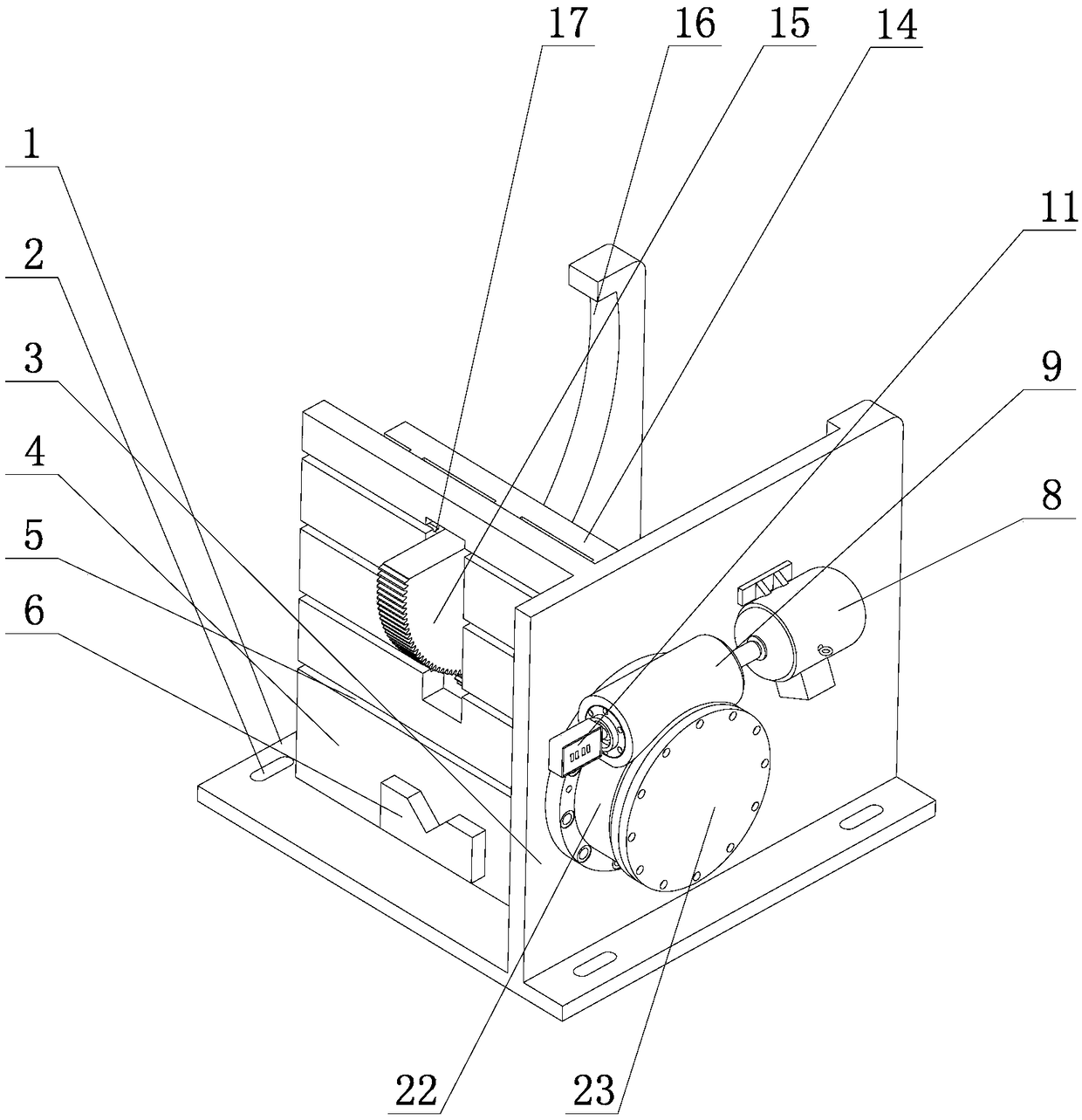
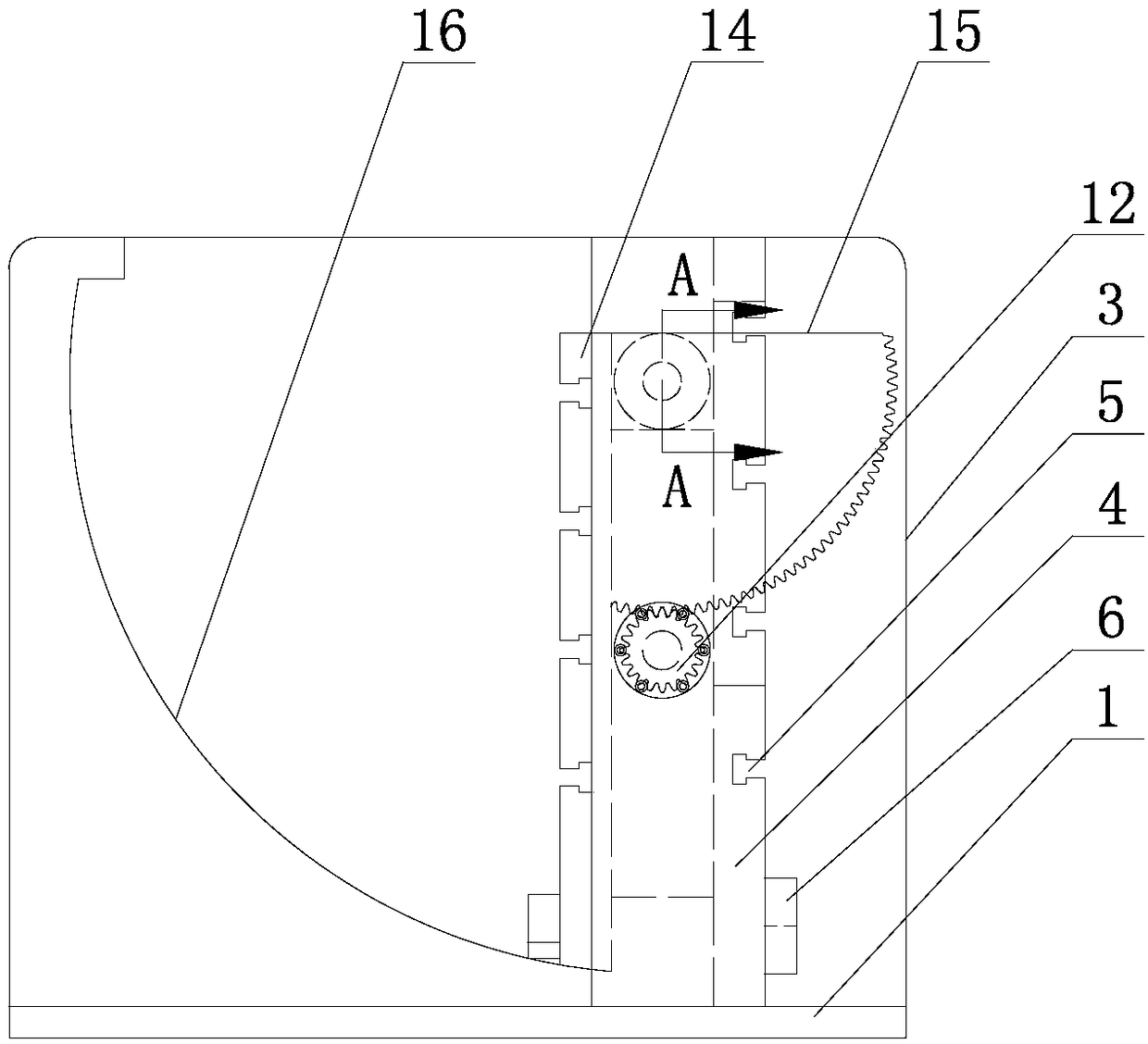
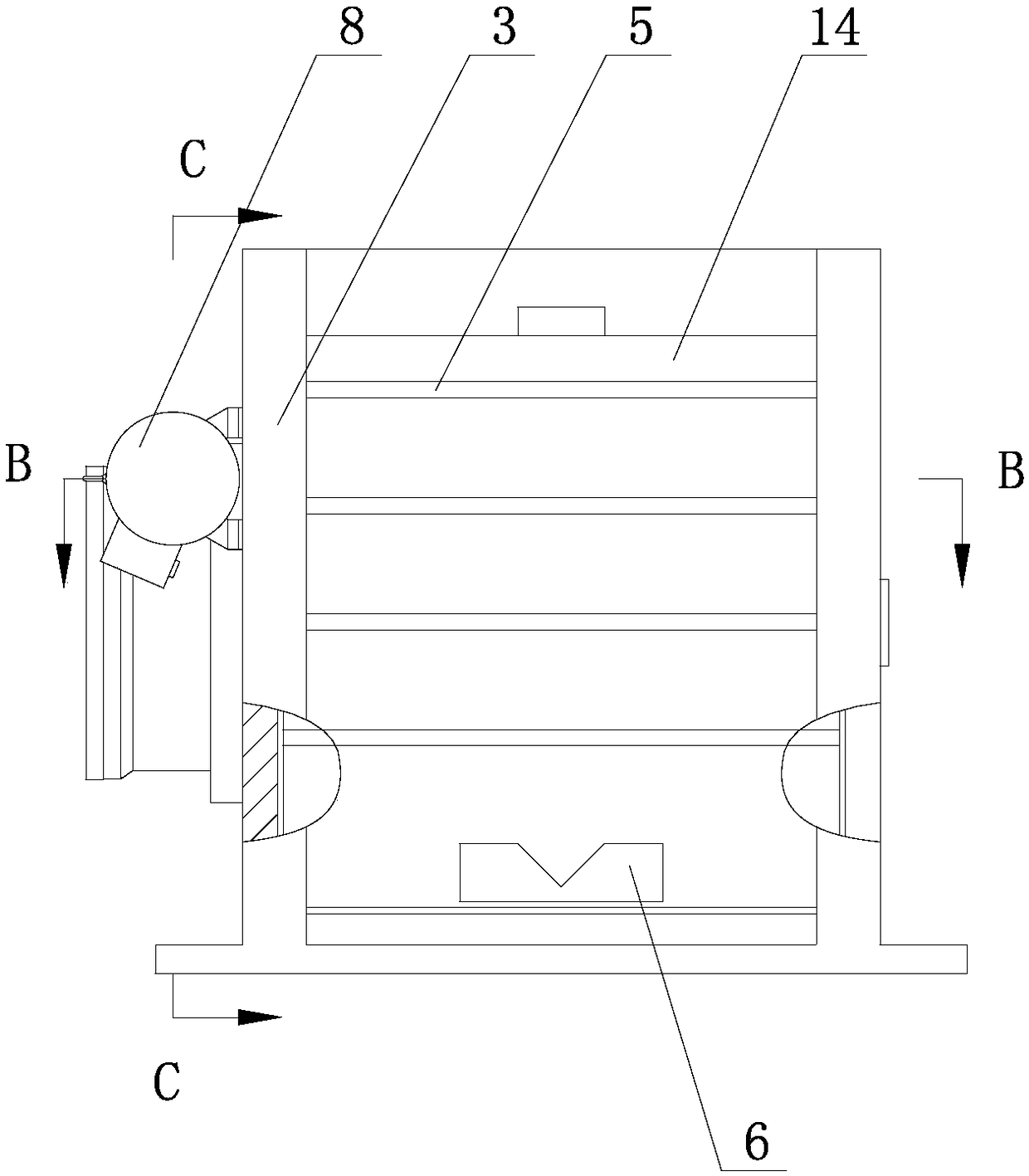
[0033] Such as Figure 1-9 As shown, a mechanical bending plate type tilt adjustment fixture includes a fixture base 1. The fixture base 1 is provided with slots 2 at four corners, and the fixture base 1 is provided with side vertical plates 3 and a middle The vertical board 4, the middle vertical board 4 is provided with a number of T-shaped grooves 5 spaced from top to bottom on the outer surface, the middle vertical board 4 is provided with a V-shaped positioning block 6 at the bottom, and the middle vertical board 4 is horizontally spaced with two The protruding bracket 7, the side vertical plate 3 is provided with a servo motor 8 on the outer surface, the servo motor 8 is connected with the worm 9, the worm 9 is connected with the worm wheel 10, the e...


PUM


Abstract

The invention provides a mechanical bent-plate-type slope adjusting clamp and method. The mechanical bent-plate-type slope adjusting clamp comprises a clamp base, wherein a side vertical plate and a middle vertical plate are arranged on the clamp base; a plurality of T-shaped grooves are formed in the outer side surface of the middle vertical plate from top to bottom in a spacing manner; a V-shaped positioning block is arranged at the bottom of the middle vertical plate; two raised brackets are horizontally arranged on the inner side surface of the middle vertical plate in a spacing manner; aservo motor is arranged on the outer side surface of the side vertical plate and connected with a worm; the worm is connected with a worm gear; an angle displayer is arranged at the tail end of the worm; one end of a gear shaft is mounted on the worm gear; the other end of the gear shaft penetrates through the side vertical plate and is mounted on the clamp base; the raised brackets are in hingedconnection with a rotating table plate through a hinge shaft; a fan-shaped gear is arranged on the reverse side of the rotating table plate and in meshed connection with the gear shaft; the T-shaped grooves are formed in the obverse side of the rotating table plate from top to bottom; and the V-shaped positioning blocks are arranged at the bottom of the rotating table plate. The mechanical bent-plate-type slope adjusting clamp and method have the advantages that the structure is stable, the rigidity is high, the operation is simple, the labor intensity is reduced, the working efficiency is improved, and the clamped part slope adjusting and positioning precision is high.

Description

Technical field: [0001] The invention relates to the technical field of process equipment, in particular to a mechanical bending plate type tilt adjustment fixture and a method for clamping workpieces of machine tool equipment such as drilling machines, gantry milling machines and performing vertical and oblique hole drilling or face milling processing. Background technique: [0002] At present, parts such as flywheels and support sleeves widely used on mechanical presses usually need to be machined with long and deep oblique holes, which are used to lubricate the main driving rotating parts of the mechanical press. Some disc parts also need vertical and oblique holes. Drilling or face milling. How to securely and accurately fix the flywheel, support sleeve, disc and other parts on the drilling machine or milling machine table or the base surface of the platform, and realize the drilling of slender and deep oblique holes or the milling of the surface has always troubled the techn...

Claims


Application Information

Patent Timeline
Patent Type & Authority Patents(China)
IPC IPC(8): B23Q3/04B23Q3/06
CPCB23Q3/04B23Q3/062
Inventor 邱玉良王鹏波刘军宋晓龙周红波郝玉琴王文忠刘文明王凯
Owner 荣成远海滑动轴承有限公司
Why Eureka
Try Eureka