
Push hemostatic device

A push-type and other-side technology, applied in the field of push-type rapid hemostasis devices, can solve the problems of inconvenient use, reduced effect, and inability to achieve pressure hemostasis, etc., and achieve the effect of preventing infection and low cost

Inactive Publication Date: 2016-11-23
中国人民解放军第150中心医院
View PDF7 Cites 5 Cited by
  • Summary
  • Abstract
  • Description
  • Claims
  • Application Information

AI Technical Summary

Problems solved by technology

[0002] In the process of using a puncture needle to puncture the puncture site of the arm or foot, the puncture needle usually has a certain diameter, and the tissue inserted into the blood vessel and other diseased parts can be extracted by using the inner hole of the puncture needle and the inner hole of the connected catheter for treatment , Inspection work, because after the puncture needle is used and pulled out, a tourniquet should be used to stop the bleeding. The commonly used tourniquet in the hospital is a balloon tourniquet made in Japan "Application Publication No., JP2002323940; Publication Date, June 3, 2004" , the patent needs to be used with an air syringe to inflate the balloon, and the balloon compresses the puncture site to obtain the hemostatic effect, but the patent is inconvenient to use, and because it is disposable, the medical cost of the patient is too high.” Each reaches about RMB 300"; there is also a spring type made in Japan "Chinese Patent Application Publication No. CN103027724A". The pad part 42 of the reference sign is responsible for the observation task, so it is made as a flat ground, which is affected by human bones. In the actual operation process, it cannot be completely pressed against the compression point, resulting in a reduced effect, and it cannot achieve real pressure to stop bleeding.

Method used


Image

  • Push hemostatic device
  • Push hemostatic device
  • Push hemostatic device

Examples


Embodiment Construction

[0024] The present invention can be explained in more detail by the following examples, and the purpose of disclosing the present invention is intended to protect all changes and improvements within the scope of the present invention, and the present invention is not limited to the following examples;

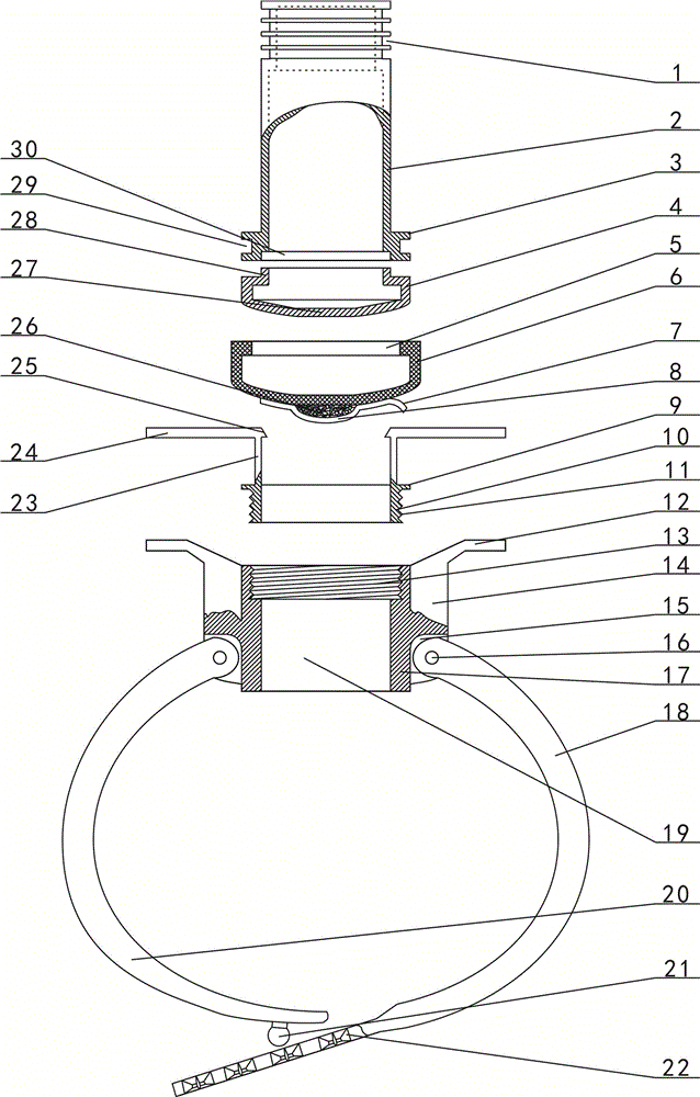
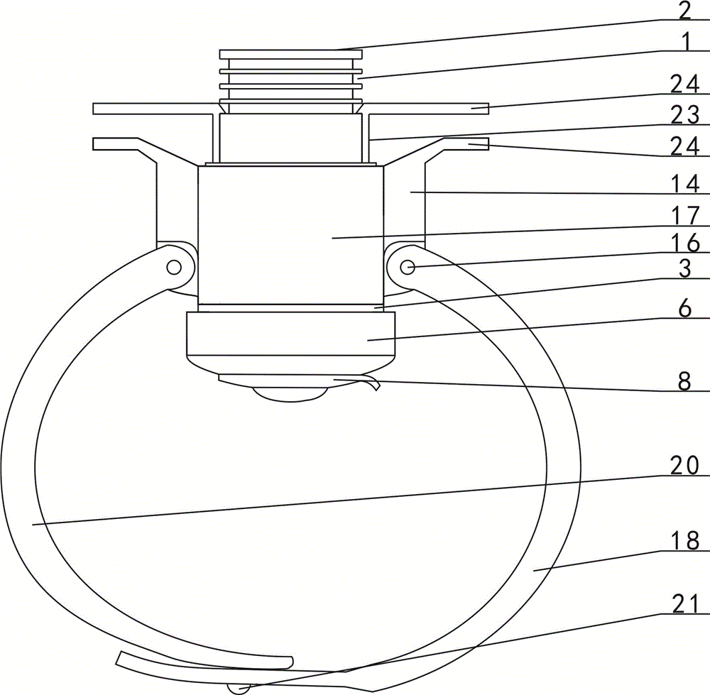
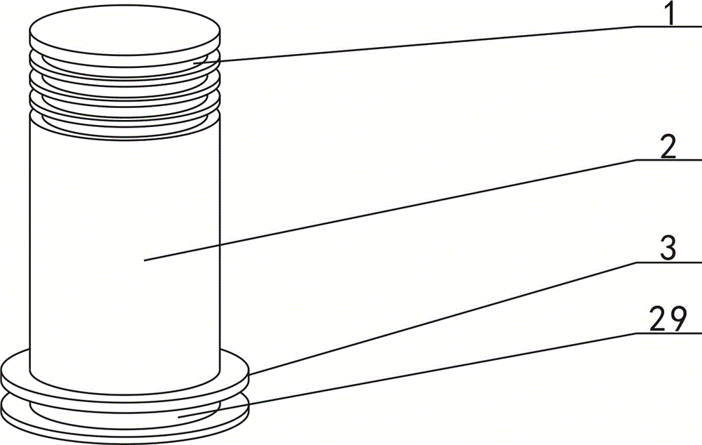
[0025] combined with Figure 1~6 The push-type hemostatic device includes a collar 17, a belt 18 on one side, a belt 20 on the other side, a pressing cylinder 2 and a silicone rubber sleeve 6, and side protruding blocks 14 are respectively arranged on both sides of the collar 17. The outer sides of the upper end of both sides of the protruding block 14 are respectively provided with a finger lifter 12; one end of a side belt 18 is provided with a gap 32, and the both sides of the side belt 18 gap 32 are respectively provided with a shaft hole 31, and one side of the belt 18 Gap 32 is stuck on the connecting plate 15 of collar 17 one side protruding block 14 bottoms, and shaft 1...


PUM


Abstract

The invention relates to a hemostatic instrument, in particular to a push hemostatic device. The lower portions of two sides of a loop (17) are connected respectively with one end of a strap (1) on one side and one end of a strap (20) on the other side, two sides of an upper opening of an inner hole (19) of the loop are provided respectively with vertical rods (23), the outer sides of the upper ends of the two vertical rods are provided respectively with press rods (24), the inner sides of the upper ends of the two vertical rods are provided respectively with hooks (25), the middle of a push tube (2) runs through the inner hole of the loop, two sides of the upper portion of the push tube are provided with a plurality of locking slots spaced from top to bottom, the outer edge of the lower end of the push tube is provided with a circular protrusion (3), and an inner convex ring plate (5) at an upper opening of a silicone rubber sleeve (6) sleeves a circular groove B (29) arranged in the outer edge of the circular protrusion of the push tube; absorbent cotton at the lower portion of the silicone rubber sleeve arranged at the lower end of the push tube is utilized to achieve hemostasis; since the silicone rubber sleeve is disposable, the cost of use is relatively low and hemostatic effect is good.

Description

【Technical field】 [0001] The invention relates to a hemostatic device, in particular to a pressing type rapid hemostatic device. 【Background technique】 [0002] In the process of using a puncture needle to puncture the puncture site of the arm or foot, the puncture needle usually has a certain diameter, and the tissue inserted into the blood vessel and other diseased parts can be extracted by using the inner hole of the puncture needle and the inner hole of the connected catheter for treatment , Inspection work, because after the puncture needle is used and pulled out, a tourniquet should be used to stop the bleeding. The commonly used tourniquet in the hospital is a balloon tourniquet made in Japan "Application Publication No., JP2002323940; Publication Date, June 3, 2004" , the patent needs to be used with an air syringe to inflate the balloon, and the balloon compresses the puncture site to obtain the hemostatic effect, but the patent is inconvenient to use, and because i...

Claims


Application Information

Patent Timeline
IPC IPC(8): A61B17/12
CPCA61B17/12A61B2017/12004
Inventor 马小桔葛雪燕马素飒李冠海张明德杨金炜庄明军卜建学曹应江冯聪勤黄咏梅吴英超陈凤凤刘文伟赵玲艳周义娜梁涵涵张蓉智慧王璐梁英赵鹏举刘献茹刘智文
Owner 中国人民解放军第150中心医院
Learn More