Dust collection device for pyrophyllite breaking system

A technology of dust removal device and crushing system, which is applied in the direction of combination device, dispersed particle separation, chemical instruments and methods, etc., which can solve the problems of dust affecting air quality, etc., and achieve the effects of avoiding the flow to the atmosphere, saving costs and reducing consumption

Active Publication Date: 2016-11-23
邵阳市东昇超硬材料有限公司
View PDF6 Cites 0 Cited by
  • Summary
  • Abstract
  • Description
  • Claims
  • Application Information

AI Technical Summary

Problems solved by technology

[0004] The invention provides a dust removal device for a pyrophyllite crushing system, aiming to solve the problem in the prior art that the dust generated during the pyrophyllite crushing process affects the air quality in the working environment

Method used


Image

  • Dust collection device for pyrophyllite breaking system
  • Dust collection device for pyrophyllite breaking system
  • Dust collection device for pyrophyllite breaking system

Examples


Embodiment 1

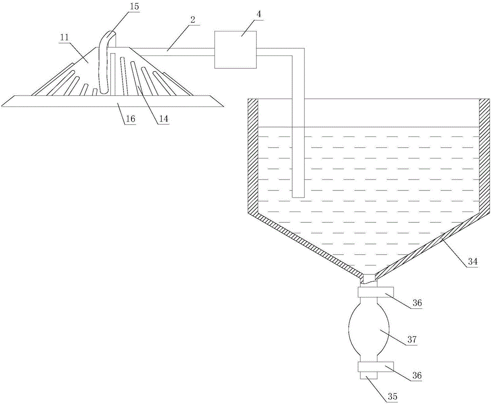
[0026] refer to figure 1 , The dedusting device for the pyrophyllite crushing system includes a dust collector, an air outlet pipe 2, an induced fan 4 and a water dust collector, and the induced fan 4 is arranged on the air outlet pipe 2.

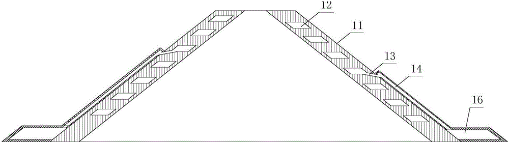
[0027] refer to figure 1 and figure 2 , the dust collector includes a body 11, a dust collection tank 16 and a connecting pipe 15. The body 11 is in the shape of a trumpet with a small upper part and a larger lower part. Connected dust discharge channels 13, each dust discharge channel 13 lower end is connected with a dust discharge pipe 14, each dust discharge pipe 14 lower end is connected with a dust collection groove 16, and the dust collection groove 16 surrounds the outer wall of the lower end of the body 11 .

[0028] refer to figure 1 , the water dust collector includes a water tank 34 and a storage pipe 35, the lower bottom surface of the water tank 34 is a tapered surface with a large upper part and a smaller lower part, the ...

Embodiment 2

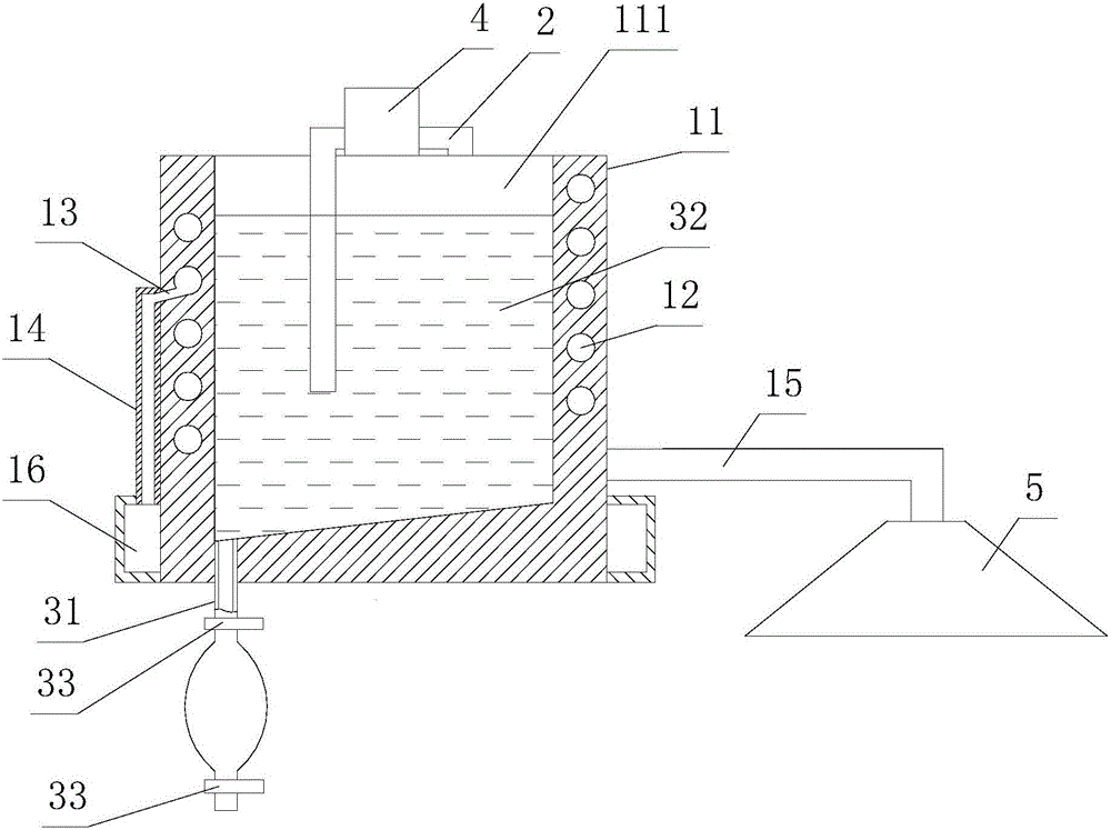
[0033] refer to image 3 and Figure 4 , the dedusting device for the pyrophyllite crushing system, including a dust collector, an air outlet pipe 2, an induced draft fan 4, a water dust collector and a dust collection cover 5, and the induced draft fan 4 is arranged on the air outlet pipe 2;

[0034] refer to image 3 and Figure 4 The dust collector includes a body 11, a dust collection tank 16 and a connecting pipe 15. The body 11 is cylindrical and has a cavity 111 with an upward opening. The body 11 is provided with a cylindrical spiral channel 12 arranged on the inner wall of the channel 12. There is a dust discharge channel 13 communicating with the channel 12, and the lower end of each dust discharge channel 13 is connected with a dust discharge pipe 14. on the outer wall of the

[0035] refer to image 3 , the channel 12 is provided with an air inlet and an air outlet, the air inlet is arranged at the lower end of the outer wall of the body 11, and the air outlet...


PUM


Abstract

The invention provides a dust collection device for a pyrophyllite breaking system with an aim to solve the problem that air quality is affected by dust generated in the process of pyrophyllite breaking in the prior art. The dust collection device comprises a dust collector, an escape pipe, a draught fan and a water dust collector; the dust collector comprises a body, dust collection grooves and a connecting pipe, spiral channels are arranged in the body, dust collection channels are arrayed in inner bottoms of the channels, each dust collection channel is connected with a dust collection pipe at the lower end, each dust collection pipe is connected with one dust collection groove at the lower end, and the lower outer lateral wall of the body is encircled with the dust collection grooves. Under the action of centrifugal force, dust particles larger than air in density are thrown to side walls of the channels; under the action of the lateral-wall friction resistance, dust falls upon the bottoms of the channels and falls into the dust collection channels when moving slowly to the dust collection channels along the bottoms of the channels, the dust falling into the dust collection channels falls into the dust collection grooves via the dust collection pipes, and dusty air is treated through the dust collection channels and purified.

Description

technical field [0001] The invention relates to a dust removal device for a pyrophyllite crushing system. Background technique [0002] At present, in the process of crushing pyrophyllite with a crusher, a large amount of dust will be generated, causing air pollution, seriously affecting the working environment, and causing great harm to the staff. [0003] In order to remove the dust generated during crushing, some manufacturers currently use bag dust collectors for dust removal, but this kind of dust collectors are prone to clogging after long-term use, which affects the dust removal effect; in addition, a patent application with application number 201020254127. The crushing dust removal device, the gas with dust is dedusted by the cyclone dust collector, and the dust in the dust hopper of the dust collector passes through the water tank, and the dust is absorbed by water; but the device for collecting dust in this way, the cyclone dust collector and the water tank are all...

Claims


Application Information

Patent Timeline
Patent Type & Authority Applications(China)
IPC IPC(8): B01D50/00
CPCB01D50/40
Inventor 张俊杰
Owner 邵阳市东昇超硬材料有限公司
Why Eureka
Try Eureka