Pin puller based on memory alloy wire

A technology of memory alloy wire and pin puller, which is applied in the direction of hand-held tools and manufacturing tools, can solve the problems of low current and power-on time requirements, difficult heating of memory alloy rods, and low power of memory alloy wires, etc., to achieve reliable Safety and security are easy to guarantee, the structure is simple, and the effect of large output pulling force

Active Publication Date: 2016-11-23
AEROSPACE DONGFANGHONG SATELLITE
View PDF7 Cites 6 Cited by
  • Summary
  • Abstract
  • Description
  • Claims
  • Application Information

AI Technical Summary

Problems solved by technology

[0006] The technical problem solved by the present invention is: to overcome the deficiencies in the prior art, provide a pin puller based on memory alloy wire, solve the problem that the memory alloy wire is too small in power, and the memory alloy rod is difficult to heat, so that the present invention can pull out the pin. The pin puller can be directly energized for heating, the requirements for energizing current and energizing time are low, and the power for pulling out the pin is large. At the same time, the reliability and practicability of the pin puller of the present invention are also improved.

Method used


Image

  • Pin puller based on memory alloy wire
  • Pin puller based on memory alloy wire
  • Pin puller based on memory alloy wire

Examples


Embodiment Construction

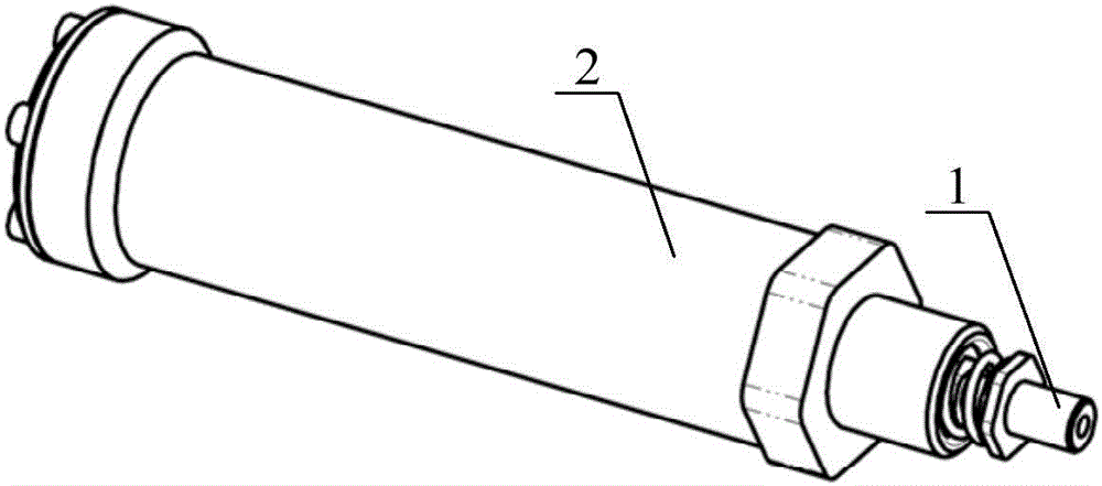
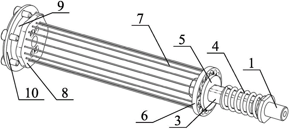
[0025] The present invention aims at the deficiency of prior art, proposes a kind of pin puller based on memory alloy wire, as figure 2 Shown is the overall outline schematic diagram of pin puller of the present invention, as image 3 Shown is a schematic diagram of the internal structure of the pin puller of the present invention, including a pin 1, a shell 2, a pull rod 3, a top spring 4, a front insulating pad 5, a pull plate 6, a memory alloy wire 7, a PCB board 8, and a rear insulating pad 9 , the rear cover 10, while the pin puller of the present invention also includes a power supply wire 11,

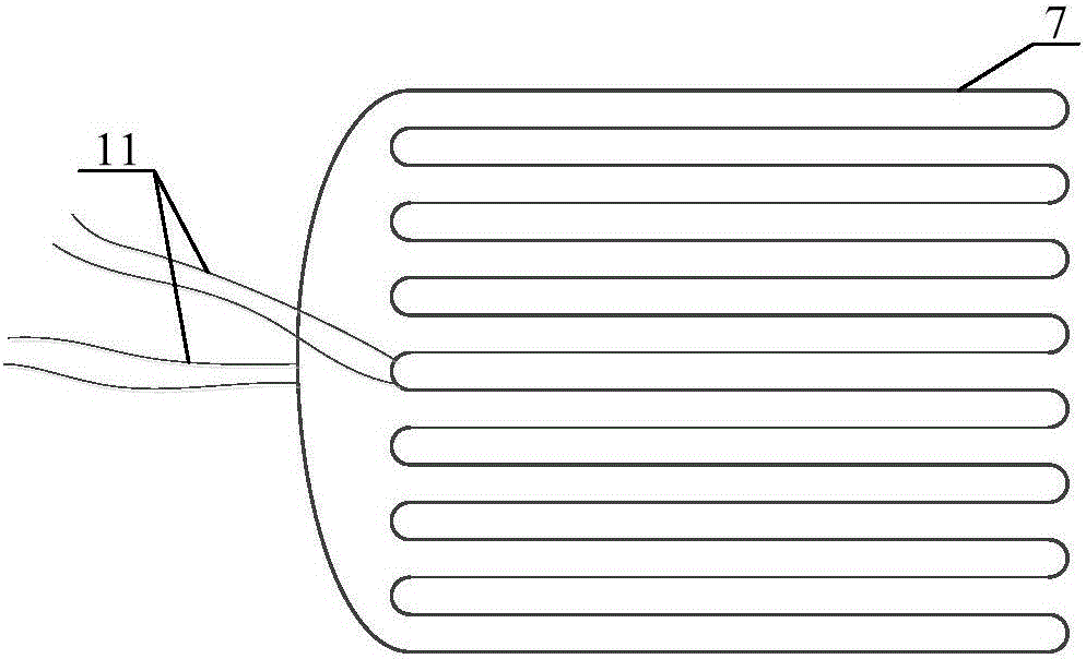
[0026] Such as figure 1 Shown is the electrical schematic diagram of the pin puller of the present invention. The memory alloy wires 7 are mechanically connected in parallel, first in series and then in parallel on the circuit. Therefore, mechanically, multiple memory alloy wires can be energized and contracted simultaneously to provide pulling force. The memory alloy wire on ...


PUM


Abstract

A pin puller based on a memory alloy wire comprises a pin, a housing, a pull rod, an ejection spring, a front insulating mat, a pull tray, a memory alloy wire, a PCB (printed circuit board), a rear cover and a service conductor, wherein two bonding pads of the PCB are conducted respectively, but not with each other; the pull rod is sleeved and fixedly connected with the front insulating mat and the pull tray; the two ends of the memory alloy wire are soldered and fixed with the PCB; the service conductor is welded on the service conductor bonding pad of the PCB and thrown out through an opening in the housing; the pull rod penetrates out of a waist-shaped hole in the housing; the pull rod is sleeved with the ejection spring; and the pin is inserted into the ejection spring and screwed into the pull rod. according to the pin puller, the problem of too small operation force of the memory alloy wire is solved by adopting the method of back-and-forth shuttling of the memory alloy wire between the pull tray and the PCB for many times; compared with the existing pin puller for an initiating explosive device, the pin puller has the advantages of low energy source requirements, large output pull and easiness in reliability and safety guarantee.

Description

technical field [0001] The invention relates to a pin puller product, in particular to a pin puller based on memory alloy wire. Background technique [0002] As a new type of intelligent material, memory alloy has the characteristics of shape memory. It is forced to deform below a specific phase transition temperature. When the temperature rises above the phase transition temperature, the memory alloy can restore its original shape. This feature of the memory alloy has good application value, and has been widely used in the fields of civilian toys, robots and aviation. [0003] When used as an operating element, the memory alloy wire generally has the following two ways of use. One is to make the memory alloy wire into a coil spring and heat it by direct electricity or hot water or hot air to deform it. The feature is that the heating is simple and the stroke is large, but the working power is very small, generally no more than a few cows; the second is to directly stretch ...

Claims


Application Information

Patent Timeline
Patent Type & Authority Applications(China)
IPC IPC(8): B25B27/02
CPCB25B27/02
Inventor 杨天光马灵犀王海明韩建斌扈勇强
Owner AEROSPACE DONGFANGHONG SATELLITE
Why Eureka
Try Eureka