Gas supply control device of forming machine main drum driving box

A control device and drive box technology, applied to tires, other household appliances, household appliances, etc., can solve the problems of inconvenient installation and replacement, the number of rotary seals, and the number of rotary seals used, so as to reduce the difficulty of processing and assembly. , The effect of reducing the frequency of replacement and reducing the cost of equipment maintenance

Inactive Publication Date: 2016-11-23
QINGDAO MESNAC ELECTROMECHANICAL ENG +1
View PDF6 Cites 2 Cited by
  • Summary
  • Abstract
  • Description
  • Claims
  • Application Information

AI Technical Summary

Problems solved by technology

[0004] In order to solve the technical problem that the existing air supply control device for the main drum drive box of the molding machine has too many rotary sealing channels and is inconvenient to install and replace, the present invention proposes an air supply control device for the main drum drive box of the molding machine, which only uses One-way rotary seal reduces the number of rotary seals used

Method used


Image

  • Gas supply control device of forming machine main drum driving box
  • Gas supply control device of forming machine main drum driving box
  • Gas supply control device of forming machine main drum driving box

Examples


Embodiment 1

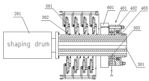
[0021] Embodiment 1, the air supply control device for the main drum drive box of the molding machine in this embodiment, such as figure 2 As shown, it includes a main shaft 301 with one end connected to the main drum drive box 201 of the molding machine. The main shaft 301 is provided with a plurality of ordinary inner holes 302 connected with the forming drum through the internal air passage of the main shaft 301 and an air source inner hole 303. The periphery of the air source inner hole 303 is provided with a rotary seal 401, the rotary seal 401 is connected to the air source (not shown in the figure), each of the common inner holes 302 is respectively connected to a solenoid valve 501, each of the The inlet end of the electromagnetic valve 501 is connected with the inner hole 303 of the air source through an air path. The working principle of this air supply control device is: the air source supplies air to the inner hole 303 of the air source through the rotary seal, an...

Embodiment 2

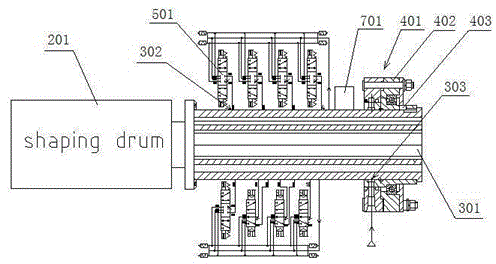
[0025] Embodiment two, such as image 3 As shown, this embodiment provides another structure of the air supply control device for the main drum drive box of the molding machine, which includes a main shaft 301 connected to the main drum drive box 201 of the molding machine at one end, and a plurality of passing main shafts are opened on the main shaft 301. 301, the ordinary inner hole 302 connected with the forming drum and an air source inner hole 303, the outer periphery of the air source inner hole 303 is provided with a rotary seal 401, and the rotary seal 401 is connected with the air source (not shown in the figure) ) connection, the common inner holes 302 are respectively connected to a solenoid valve 501, and the air intake end of each solenoid valve 501 is connected to the inner hole 303 of the air source through an air path. The difference from the first embodiment is that The outer surface of the main shaft 301 is fixed with a wireless receiving device 701 for recei...


PUM


Abstract

The invention discloses a gas supply control device of a forming machine main drum driving box. The gas supply control device comprises a main shaft, wherein one end of the main shaft is connected with the forming machine main drum driving box; a plurality of common inner holes and a gas source inner hole are formed in the main shaft; the common inner holes are connected with a forming drum through a main shaft internal gas circuit; a rotary seal is arranged on the periphery of the gas source inner hole and is connected with a gas source; each of the common inner holes is connected with a corresponding electromagnetic valve; and the air inlet of each electromagnetic valve is connected with the gas source inner hole through the gas circuit. According to the gas supply control device of the forming machine main drum driving box, the one-path rotary seal is adopted to replace the existing multi-path rotary seal, so that the device cost is reduced and the processing and assembling difficulty is also reduced; only the one-path rotary seal is provided, so that the damage frequency and the replacing frequency of the rotary seal are reduced; and in addition, one rotary seal is replaced at one time even if the rotary seal leaks air and needs to be replaced, so that the equipment maintaining cost is reduced.

Description

technical field [0001] The invention belongs to the technical field of tire building machines, and in particular relates to an air supply control device for a main drum driving box of a building machine. Background technique [0002] At present, the molding air supply method of the molding machine in the whole industry adopts a multi-channel (up to ten or more) rotary sealing method, such as figure 1 As shown, there are 10 rotary seals 101, and the air pump supplies air to each rotary seal 101 respectively, and supplies air to the forming drum through multiple deep holes in the main shaft to complete various technological actions required for tire molding. Solenoid valves 102 are arranged between the air pump and each rotary seal 101 to control the on-off of the gas circuit. The solenoid valves 102 are far away from the main shaft 103 and placed in the case or the air control cabinet. [0003] Due to the fast speed of the main shaft in the current air supply device, the ser...

Claims


Application Information

Patent Timeline
Patent Type & Authority Applications(China)
IPC IPC(8): B29D30/20
Inventor 杨慧丽徐宝信黄伟
Owner QINGDAO MESNAC ELECTROMECHANICAL ENG
Why Eureka
Try Eureka