Hydraulic height automatic adjustment device

An automatic adjustment device, hydraulic technology, applied in axle box installation, transportation and packaging, railway car body parts, etc., can solve problems such as small deflection of bogie springs, breakage of couplers, endangering driving safety, etc., to increase transportation Economic benefits, improving the force of wheel and rail parts, and easing the effect of vertical impact

Active Publication Date: 2018-03-13
CRRC YANGTZE CO LTD
View PDF8 Cites 0 Cited by
  • Summary
  • Abstract
  • Description
  • Claims
  • Application Information

AI Technical Summary

Problems solved by technology

[0007] However, the above-mentioned height adjustment device has the following disadvantages: (1) the existing non-automatic height adjustment device requires an additional power source, such as a drive motor, inflation and deflation, or manpower, which increases the complexity of the structure and the cost of manufacturing and maintenance. Moreover, some structures or products cannot be widely used due to the limitation of design size, operating environment, and even cost; (2) the existing automatic height adjustment device is limited by the height of the coupler, and the working deflection of the bogie spring is not large. The force between the wheel and rail cannot be effectively reduced; in addition, due to the height difference between the coupler between the empty and heavy vehicles, the coupler is unevenly stressed, which is likely to cause a breakage accident of the coupler and endanger the driving safety

Method used


Image

  • Hydraulic height automatic adjustment device
  • Hydraulic height automatic adjustment device
  • Hydraulic height automatic adjustment device

Examples


Embodiment Construction

[0044] The present invention will be further described in detail below in conjunction with the accompanying drawings and specific embodiments.

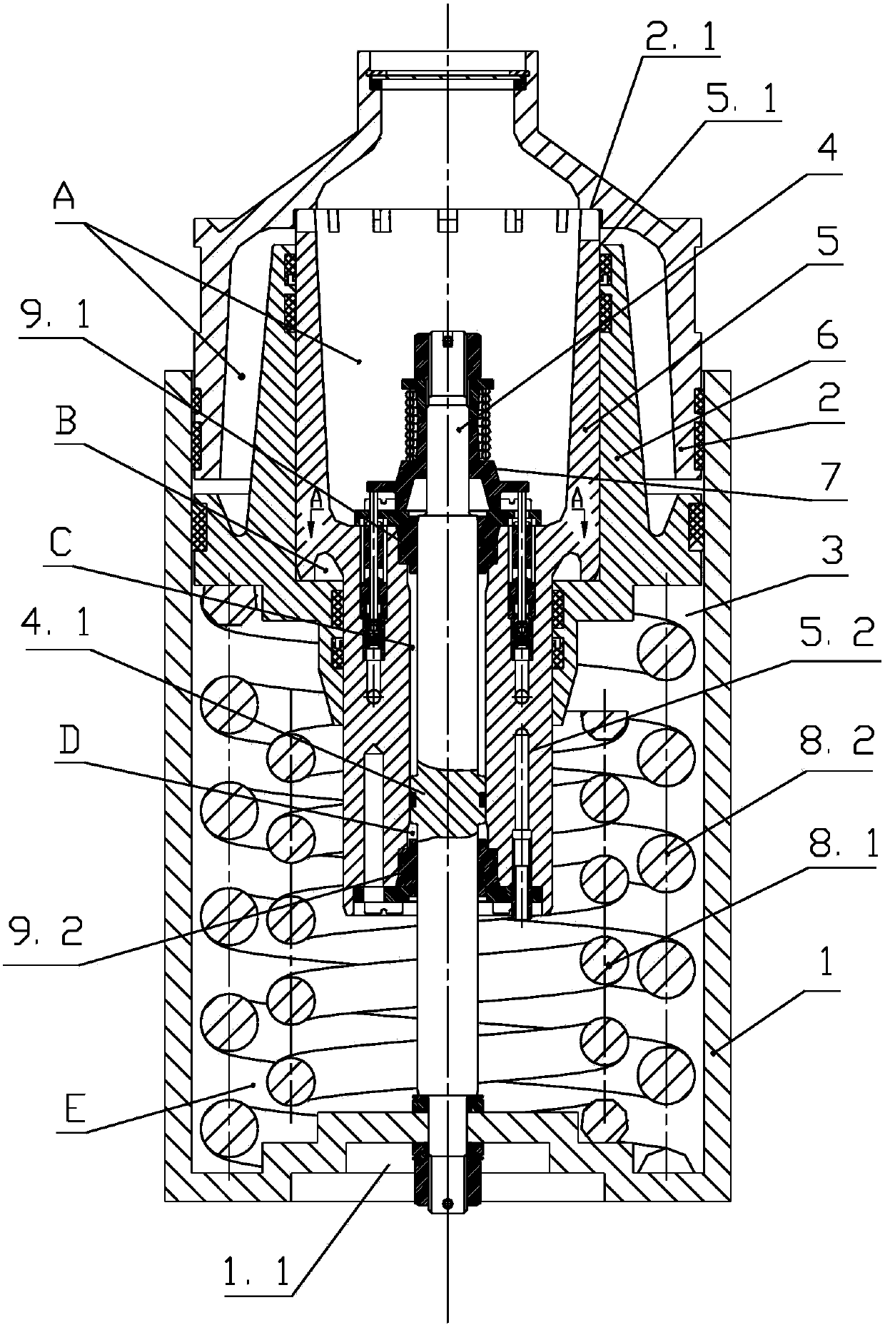
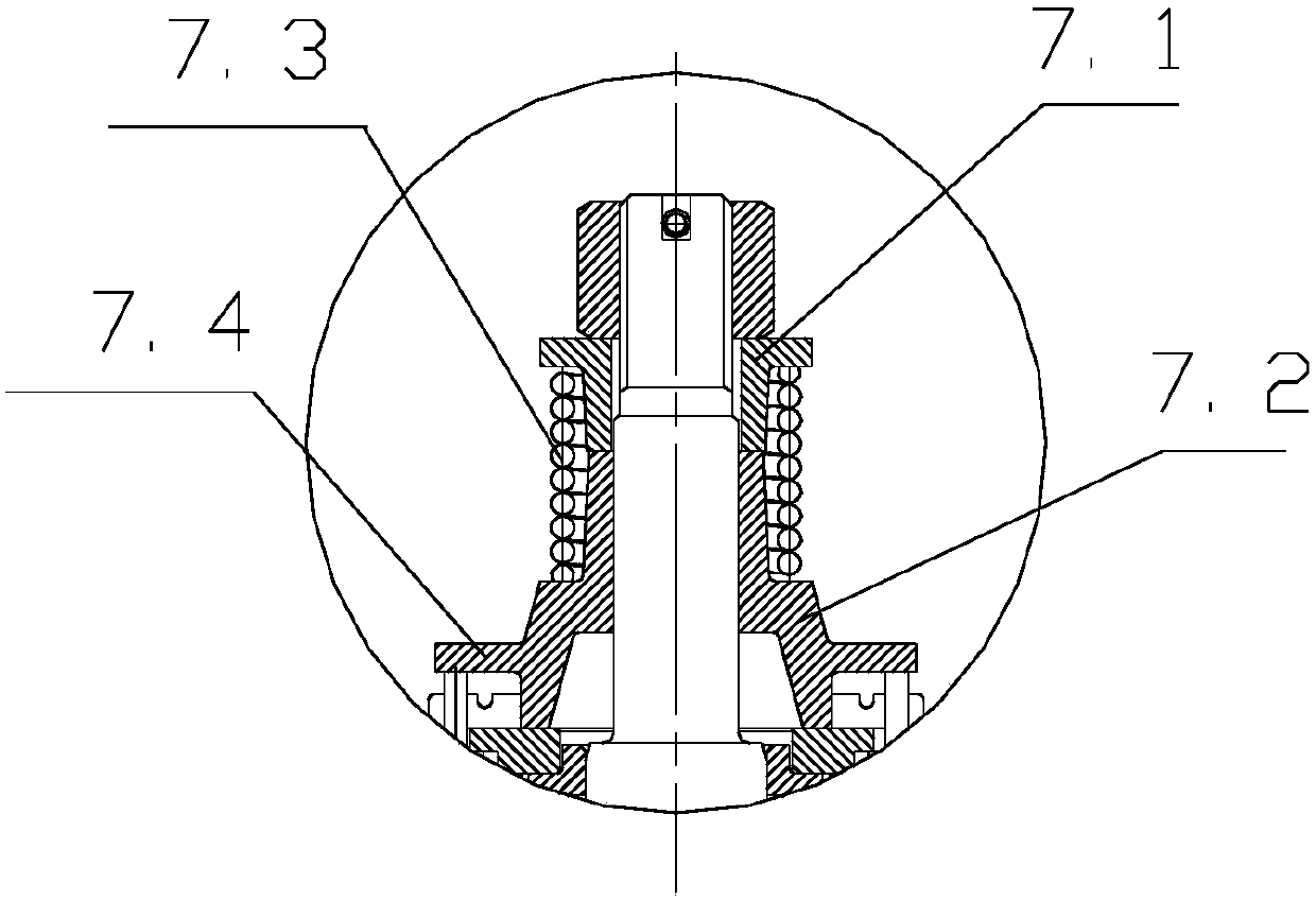
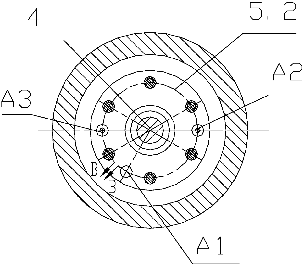
[0045] The hydraulic automatic height adjustment device shown in the figure includes a cylindrical base 1, a hollow structure top cover 2 that is arranged on the top of the base 1 and can slide up and down along its inner wall, the inner wall of the base 1 and the top cover 2 The outer wall fits together to form a sealed accommodation chamber 3; the accommodation chamber 3 is provided with a rod-shaped integral piston 4 vertically arranged with the bottom end surface of the base 1, and the outer periphery of the integral piston 4 is provided with a plunger body 5 that slides and fits with it. The top and bottom of the plunger body 5 are respectively provided with an upper seal cover 9.1 and a lower seal cover 9.2 that match the integral piston 4, the top of the plunger body 5 also extends upwards to form an annular boss 5.1, and the an...


PUM


Abstract

The invention discloses a hydraulic automatic height adjustment, comprising a tubular base and a hollow top cover arranged at the top of the base and capable of sliding up and down along an inner wall of the base, wherein the inner wall of the base and an outer wall of the top cover are attached to form a sealed receiving cavity, a rod-structure integral piston perpendicular to the bottom end surface of the base is arranged in the receiving cavity, the outer periphery of the integral piston is provided with a plunger body in sliding fit with the piston, the top and bottom of the plunger body are provided respectively with an upper seal cover and a lower seal cover mating with the integral piston, and the top of the plunger body is also extended up to form a circular boss. The volume of each hydraulic oil cavity in a vehicle is changed by vertical reciprocation, hydraulic oil is thereby driven to directionally flow in five hydraulic oil cavities by using pressure differences, vertical height is automatically adjusted, and the potential hazard where hook breakage is caused due to a hook height difference between an empty vehicle and a heavily-loaded vehicle.

Description

technical field [0001] The invention relates to an automatic height adjustment device suitable for railway vehicles, in particular to a hydraulic automatic height adjustment device. Background technique [0002] In the prior art, devices for height adjustment are mainly divided into two types: non-automatic and automatic: [0003] (1) Non-automatic height adjustment device [0004] The non-automatic height adjustment device specifically refers to the device that requires additional power to realize the height adjustment function, including the following forms: (1) Mechanical structure: For example, the invention patent with the patent application number of 201210352451.2 discloses a height adjustment device, the height adjustment device Adjust the height of the support bar through the wedge moving device; (2) Pneumatic structure: For example, the invention patent with the patent application number 201210265800.7 discloses a tractor height automatic adjustment device includi...

Claims


Application Information

Patent Timeline
Patent Type & Authority Patents(China)
IPC IPC(8): B61F5/30B61F5/26
CPCB61F5/26B61F5/30B61F5/305B61F5/308
Inventor 曹阳唐应文胡海平刘凤伟姜瑞金汤楚强王宝磊徐勇神圣
Owner CRRC YANGTZE CO LTD
Why Eureka
Try Eureka