Rapidly started and stopped garbage conveying device

A garbage conveying and fast technology, applied in the direction of conveyors, transportation and packaging, packaging, etc., can solve the problems of high energy consumption of fuel engines, limited working capacity, slow start and stop speed, etc., to achieve simple and practical structure, prevent overload, fast action effect

Active Publication Date: 2016-11-23
泰州市龙泽环境科技有限公司
View PDF7 Cites 4 Cited by
  • Summary
  • Abstract
  • Description
  • Claims
  • Application Information

AI Technical Summary

Problems solved by technology

[0002] In the field of waste transportation, the commonly used driving force of the pushing device is electric, pneumatic and fuel engine. These driving methods have their own advantages and disadvantages: electric drive has a good fast start and stop function, but it consumes a lot of power. The operating cost is high; the energy consumption of pneumatic drive is small, but the working ability is limited; although the energy consumption of fuel engine is relatively high, it has a good driving force for large quantities of garbage, but the disadvantage is that the start and stop speed is relatively slow

Method used


Image

  • Rapidly started and stopped garbage conveying device
  • Rapidly started and stopped garbage conveying device
  • Rapidly started and stopped garbage conveying device

Examples


Embodiment 1

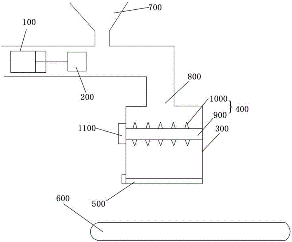
[0024] Such as figure 1 A garbage conveying device with fast start and stop shown includes a power cylinder 100, a pusher 200, a transfer box 300, a breaker 400, an electric discharge gate 500 and a conveyor belt 600; the pusher 200 and the power cylinder The pistons of 100 are connected, and the power cylinder 100 uses fuel injection to drive the piston to move so as to drive the pusher 200 to move; the garbage falls from the lower opening of the garbage bucket 700 and is pushed to the transfer port 800 by the pusher 200, and then falls into the The transfer box 300; the breaker 400 includes a rotating shaft 900 and an edge knife 1000 installed on the rotating shaft. The rotating shaft 900 driven by a motor 1100 is arranged horizontally. The garbage falling from the transfer port 800 is broken by the rotating edge knife 1000 during the falling process , and then fall into the transfer space at the lower part of the transfer box 300. The electric discharge door 500 is arranged a...

Embodiment 2

[0032] Such as figure 1 A garbage conveying device with fast start and stop shown includes a power cylinder 100, a pusher 200, a transfer box 300, a breaker 400, an electric discharge gate 500 and a conveyor belt 600; the pusher 200 and the power cylinder The pistons of 100 are connected, and the power cylinder 100 uses fuel injection to drive the piston to move so as to drive the pusher 200 to move; the garbage falls from the lower opening of the garbage bucket 700 and is pushed to the transfer port 800 by the pusher 200, and then falls into the The transfer box 300; the breaker 400 includes a rotating shaft 900 and an edge knife 1000 installed on the rotating shaft. The rotating shaft 900 driven by a motor 1100 is arranged horizontally. The garbage falling from the transfer port 800 is broken by the rotating edge knife 1000 during the falling process , and then fall into the transfer space at the lower part of the transfer box 300. The electric discharge door 500 is arranged...

Embodiment 3

[0040] Such as figure 1 A garbage conveying device with fast start and stop shown includes a power cylinder 100, a pusher 200, a transfer box 300, a breaker 400, an electric discharge gate 500 and a conveyor belt 600; the pusher 200 and the power cylinder The pistons of 100 are connected, and the power cylinder 100 uses fuel injection to drive the piston to move so as to drive the pusher 200 to move; the garbage falls from the lower opening of the garbage bucket 700 and is pushed to the transfer port 800 by the pusher 200, and then falls into the The transfer box 300; the breaker 400 includes a rotating shaft 900 and an edge knife 1000 installed on the rotating shaft. The rotating shaft 900 driven by a motor 1100 is arranged horizontally. The garbage falling from the transfer port 800 is broken by the rotating edge knife 1000 during the falling process , and then fall into the transfer space at the lower part of the transfer box 300. The electric discharge door 500 is arranged...


PUM


Abstract

The invention discloses a rapidly started and stopped garbage conveying device. The rapidly started and stopped garbage conveying device comprises a power cylinder, a material pushing device, a transferring box, a crusher, an electric material discharge door and a conveyor belt, wherein the material pushing device is connected with the piston of the power cylinder; an oil injection combustion mode is adopted by the power cylinder to drive the piston to move, so that the material pushing device is driven to move; garbage falls from the lower opening of a garbage hopper, is pushed to a transferring port by the material pushing device, and then falls into the transferring box; the crusher comprises a rotary shaft and an edge cutter arranged on the rotary shaft; the rotary shaft is driven by a motor and is horizontally arranged; the garbage falling from the transferring port is crushed by the rotating edge cutter during falling, then falls into a transferring space on the lower part of the transferring box; the electric material discharge door is arranged on the bottom of the transferring box; a weight sensor is arranged on the electric material discharge door; and when the garbage in the transferring space reaches a certain value, the electric material discharge door is opened automatically, so that the garbage falls onto the conveyer belt to be carried away.

Description

technical field [0001] The invention relates to the field of garbage conveying, in particular to a garbage conveying device with fast start and stop. Background technique [0002] In the field of waste transportation, the commonly used driving force of the pushing device is electric, pneumatic and fuel engine. These driving methods have their own advantages and disadvantages: electric drive has a good fast start and stop function, but it consumes a lot of power. The operating cost is high; the energy consumption of pneumatic drive is small, but the working ability is limited; although the energy consumption of fuel engine is relatively high, it has a good driving force for large quantities of garbage, but the disadvantage is that the start and stop speed is relatively slow . In addition, how to rationally arrange equipment such as garbage conveying and crushing is also a problem of considerable use value. Contents of the invention [0003] In view of the above problems, ...

Claims


Application Information

Patent Timeline
Patent Type & Authority Applications(China)
IPC IPC(8): B65G65/44B65G69/14B65G65/42B65D90/66
CPCB65D90/66B65G65/42B65G65/44B65G69/14B65G2201/04
Inventor 不公告发明人
Owner 泰州市龙泽环境科技有限公司
Why Eureka
Try Eureka