Automatic bottom thread changing control method of computer embroidery machine

A control method and technology for embroidery machines, which can be applied to embroidery machines, embroidery machine mechanisms, textiles and papermaking, etc., can solve problems such as a large number of human resources and affect the working efficiency of embroidery machines.

Inactive Publication Date: 2016-11-23
ZHEJIANG YUELONG SEWING EQUIP
View PDF10 Cites 1 Cited by
  • Summary
  • Abstract
  • Description
  • Claims
  • Application Information

AI Technical Summary

Problems solved by technology

[0002] At present, for the embroidery machine industry, the bobbin case is an important device for accommodating the bottom thread, which needs to be replaced frequently. At present, if manual replacement is adopted, it not only requires a lot of human resources, but also requires a long shutdown operation, which greatly affects the normal working efficiency of the embroidery machine.
There are also some devices or methods for automatically changing the bottom thread, but most of them have more faults and uncertainties, that is, they do not know where the fault occurs or continue to perform the function of changing the bottom thread after the fault, and many other disadvantages , how to realize the high precision and accuracy of the computerized embroidery machine automatic bobbin thread changing control method has always been the object of research by those skilled in the art

Method used


Image

  • Automatic bottom thread changing control method of computer embroidery machine
  • Automatic bottom thread changing control method of computer embroidery machine
  • Automatic bottom thread changing control method of computer embroidery machine

Examples


Embodiment Construction

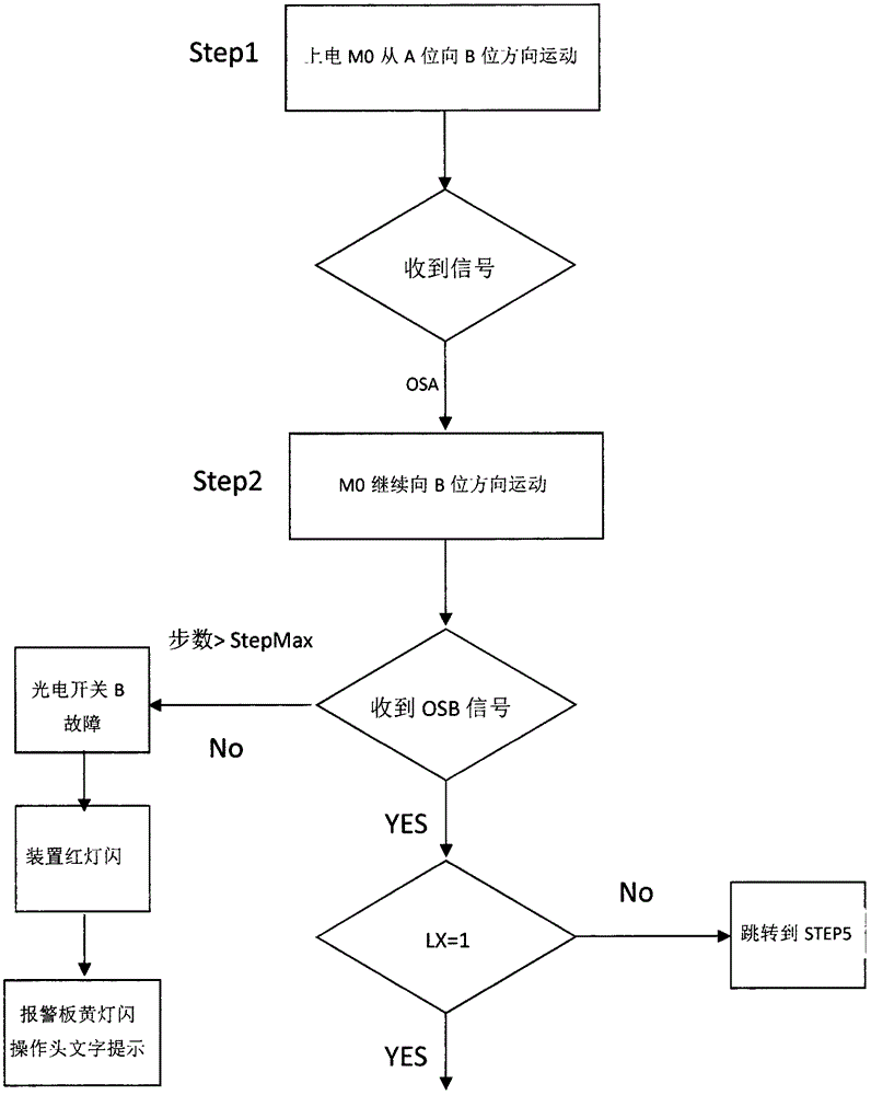
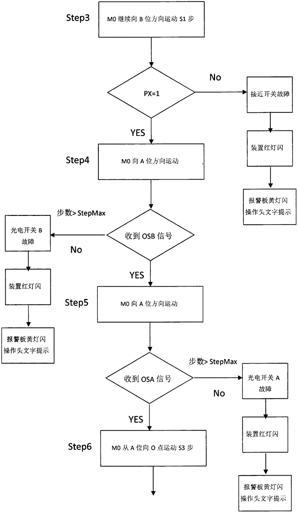
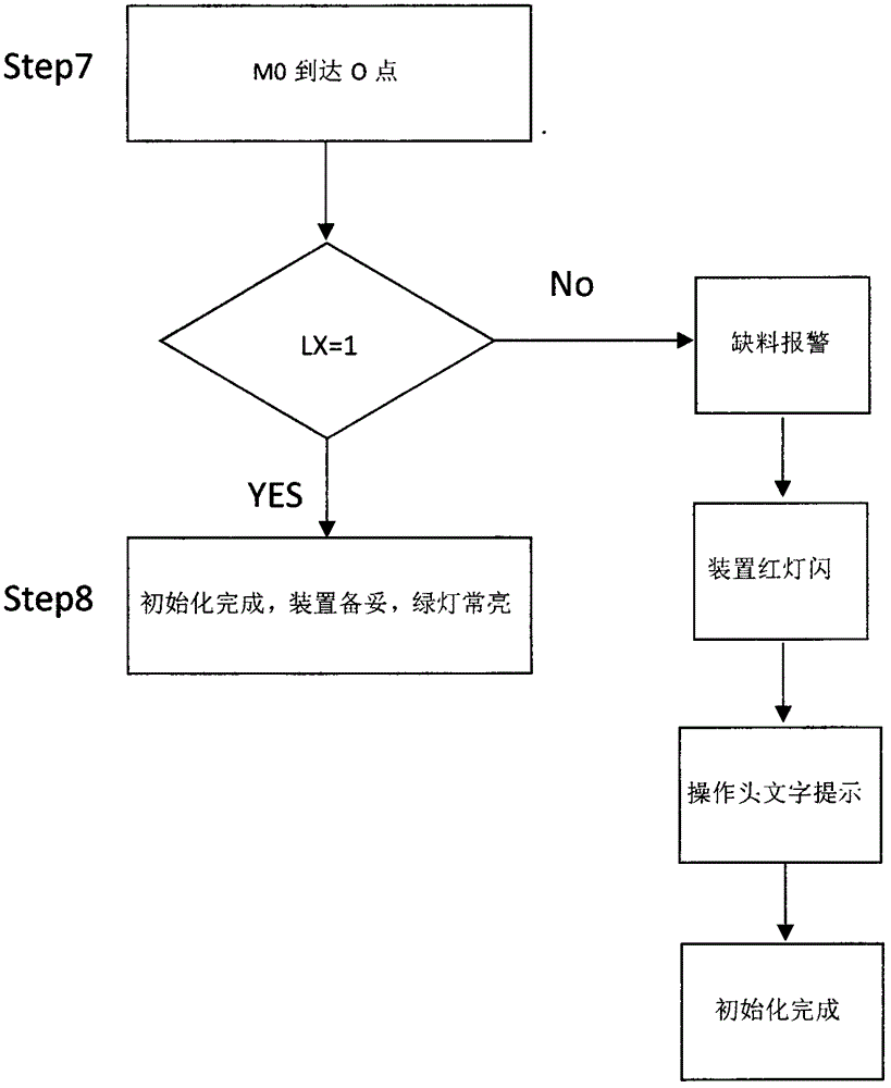
[0083] Such as Figure 1-14 Shown is a control method for automatic bobbin thread change of a computerized embroidery machine, which includes two parts: the first part is the initialization part, and the second part is the main program part

[0084] In the initialization part, after the automatic bobbin thread changing device is powered on, the stroke stepping motor moves from the rotary hook position to the spare bobbin case installation position. During this process, the photoelectric switch of the rotary hook position and the photoelectric switch of the spare bobbin case position feeds back the signal, and judges whether the sensor has fault; at the same time, use the signal of the spare bobbin case micro switch to judge whether the bobbin case has been installed in the spare position, and use the installed bobbin case to detect whether the proximity switch of the grabbing arm is faulty; judge the stroke step while detecting whether each sensor is faulty. Enter the position...


PUM


Abstract

The invention discloses an automatic bottom thread changing control method of a computer embroidery machine. The automatic bottom thread changing control method includes two parts, wherein the first part is an initializing part, and the second part is main procedure part. In the initializing part, after an automatic bottom thread changing device is powered on, a travel stepping motor moves to a backup bobbin case installation position from a bobbin rotating position, and the position of the travel stepping motor is judged while whether a fault exists in sensors is detected; finally, the stepping motor is positioned at a preset position, stopped and locked, and the whole initializing process is completed. In the main procedure part, the travel stepping motor walks to the bobbin rotating position through positioning of a bobbin rotating position photoelectric switch, performs the bobbin case grabbing action, then walks to a bobbin case releasing position in a positioned mode to perform the bobbin case releasing action, then grabs a backup bobbin case, returns to the bobbin rotating position to install the bobbin case and finally is positioned and stopped at the stopping position and performs self-locking, and the automatic bottom thread changing function is completed. According to the method, by performing the the two-procedure method of the initializing part and the main procedure part, the grabbing efficiency is greatly improved, the success rate of releasing the bobbin case is greatly increased, and the fault alarming function is achieved.

Description

technical field [0001] The invention relates to a thread changing method for an embroidery machine, in particular to a control method for automatically changing the bottom thread of a computerized embroidery machine. Background technique [0002] At present, for the embroidery machine industry, the bobbin case is an important device for accommodating the bottom thread and needs to be replaced frequently. At present, if manual replacement is adopted, not only a large amount of human resources are required, but also long-term shutdown operations are required, which greatly affects the normal working efficiency of the embroidery machine. There are also some devices or methods for automatically changing the bottom thread, but most of them have more faults and uncertainties, that is, they do not know where the fault occurs or continue to perform the function of changing the bottom thread after the fault, and many other disadvantages How to realize the high precision and accuracy ...

Claims


Application Information

Patent Timeline
Patent Type & Authority Applications(China)
IPC IPC(8): D05C11/16
CPCD05C11/16
Inventor 陈天池
Owner ZHEJIANG YUELONG SEWING EQUIP
Why Eureka
Try Eureka