Delivery window achieving mechanical interlocking

A technology of mechanical interlock and transfer window, which is applied in the field of hospital transfer windows, can solve the problems of complex electronic interlock structure of front door and back door, easy to be affected by temperature and environment, and interlock failure of front door and back door, so as to facilitate production and manufacturing. The effect of quality management, good stability in use, and simple structure

Active Publication Date: 2016-11-23
常州市浩东净化设备科技有限公司
View PDF6 Cites 6 Cited by
  • Summary
  • Abstract
  • Description
  • Claims
  • Application Information

AI Technical Summary

Problems solved by technology

However, the disadvantages of electronic interlocks are:
[0004] 1. As we all know, the reliability of electronic equipment is poor, and the electronic components of the electronic interlock are easily affected by temperature and environment, and the interlock between the front door and the back door fails;
[0005] 2. The structure of the electronic interlocking of the front door and the back door is relatively complicated, which increases the cost of use and requires the use of a power supply; when the power is cut off, it cannot be used, especially for the smooth progress of the operation in the operating room, which will have a great impact

Method used


Image

  • Delivery window achieving mechanical interlocking
  • Delivery window achieving mechanical interlocking
  • Delivery window achieving mechanical interlocking

Examples


Embodiment Construction

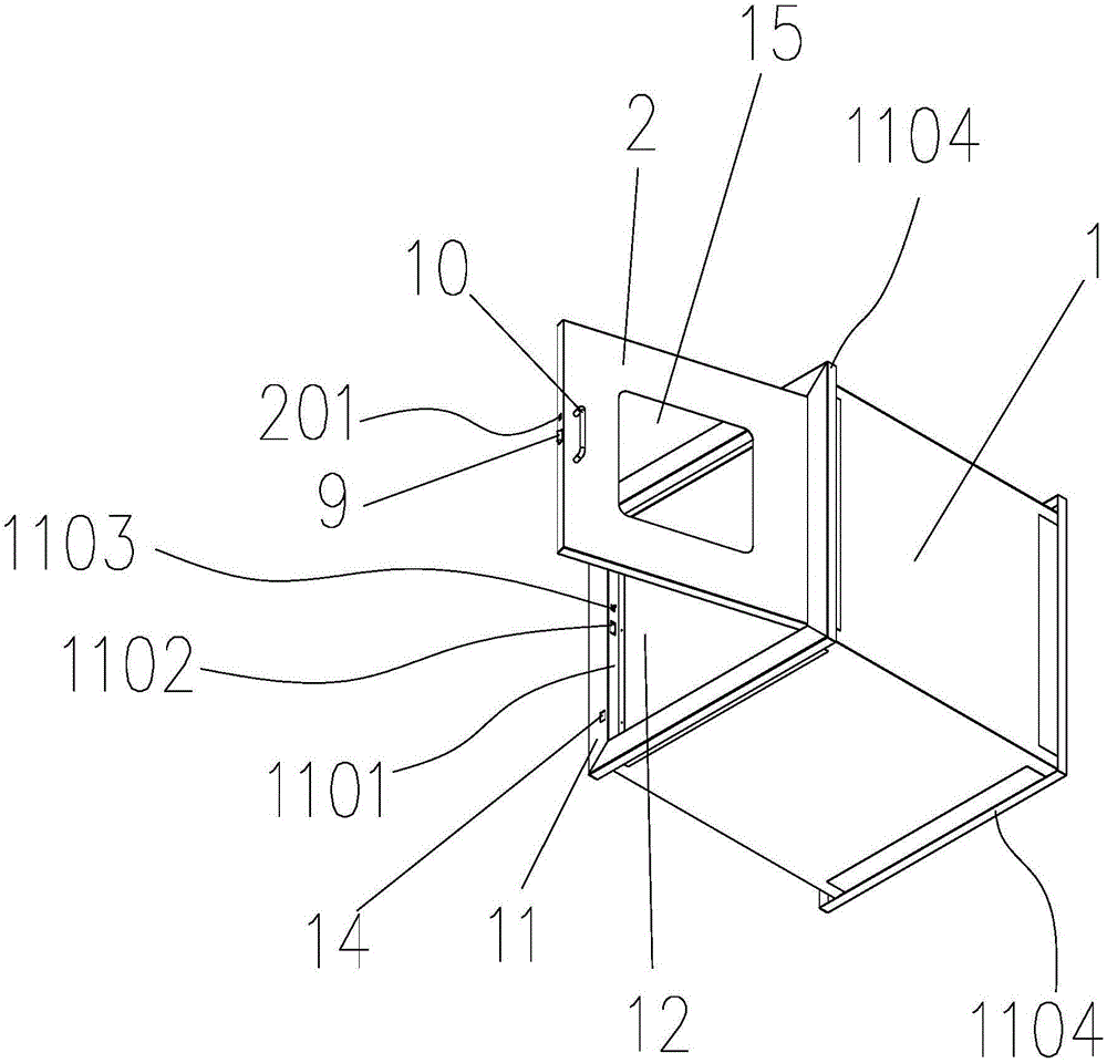
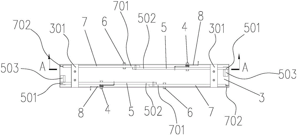
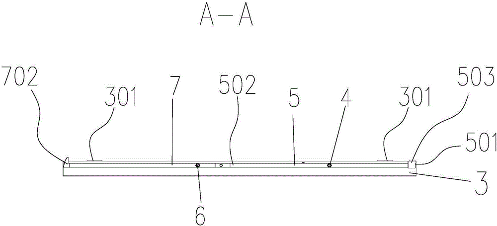
[0042] The present invention is described in further detail now in conjunction with accompanying drawing. These drawings are all simplified schematic diagrams, and only illustrate the basic structure of the present invention in a schematic manner, so they only show the configurations related to the present invention.

[0043] Such as Figure 1-Figure 12 Shown is a specific embodiment of a mechanical interlock transfer window of the present invention, which includes a cabinet body 1, the front and rear sides of the cabinet body 1 are hinged with single doors 2; the rotation centerlines of the two single doors 2 are located in the cabinet body 1 On the same side, a U-shaped groove 3 with both ends facing the single door 2 is installed on the inner surface of the cabinet body 1 away from the center line of rotation of the single door 2, and the two groove walls of the U-shaped groove 3 are connected by the first fixed shaft 4 in rotation There are first connecting rods 5, and th...


PUM


Abstract

The invention belongs to the field of hospital delivery windows, and particularly relates to a delivery window achieving mechanical interlocking. The delivery window comprises a cabinet, and singly-opened doors are hinged to the front face and the back face of the cabinet; the rotating central lines of the two singly-opened doors are located on the same side, the inner side face of the cabinet is provided with a U-shaped groove, and the two groove walls of the U-shaped groove are rotatably connected with first connecting rods and second connecting rods; the two ends of each first connecting rod are the press tongue end and the first hinge end, and each first fixing shaft is sleeved with a torsion spring; the two ends of each second connecting rod are the second hinge end and the latch hook end, second fixing shafts are located between the latch hook ends and the second hinge ends, and the second hinge ends are hinged to the first hinge ends; each singly-opened door is provided with a spring bolt and a lock opening groove used for being connected with the latch hook ends in a clamped mode. The delivery window has the advantages that a mechanical interlocking mechanism is completely adopted, no electric interlocking device is arranged, the reliability is high, the delivery window cannot be affected by the temperature and the environment, interlocking failure of the two doors cannot be caused, mechanical delivery is flexible, and the using stability is good; the structure is simple, the cost is reduced, and the delivery window does not need to be driven by a power supply.

Description

technical field [0001] The invention belongs to the field of hospital transfer windows, in particular to a mechanical interlock transfer window. Background technique [0002] Generally, hospitals have many clean rooms with very high environmental cleanliness requirements, such as operating rooms, hospital central supply rooms, laboratories, etc., as an auxiliary equipment for clean rooms, the transfer window is mainly used in clean areas, clean areas, and non-clean areas. Transfer of small items (drugs, injections, medical equipment, etc.) between the clean area and the clean area to reduce the number of times the clean room is opened and minimize the pollution of the clean area. [0003] In the prior art, the front door and the back door of the transmission window are electronically interlocked. When the front door is opened, the back door cannot be opened. At the same time, when the back door is opened, the front door cannot be opened, which acts as an airlock to prevent u...

Claims


Application Information

Patent Timeline
Patent Type & Authority Applications(China)
IPC IPC(8): E06B5/00E06B7/30E05B1/00
CPCE05B1/0015E06B5/00E06B7/30
Inventor 吴克东
Owner 常州市浩东净化设备科技有限公司
Why Eureka
Try Eureka